
Efficient concrete pouring machine

A technology for concrete and pouring machines, which is applied in the field of plastic processing, and can solve problems such as ineffective pouring machines, increased head, and large twin-screw space.

Pending Publication Date: 2020-05-12
合肥市日月新型材料有限公司
View PDF1 Cites 2 Cited by
  • Summary
  • Abstract
  • Description
  • Claims
  • Application Information

AI Technical Summary

Problems solved by technology

In the above-mentioned patents, twin-screws are used for conveying and pouring. Although the purpose of increasing the head can be achieved, the effect is not obvious for pouring machines with hoses. Due to the use of twin-screws, the space between the twin-screws in the barrel is too large. Large, so that the delivery effect is reduced

Method used


Image

  • Efficient concrete pouring machine
  • Efficient concrete pouring machine
  • Efficient concrete pouring machine

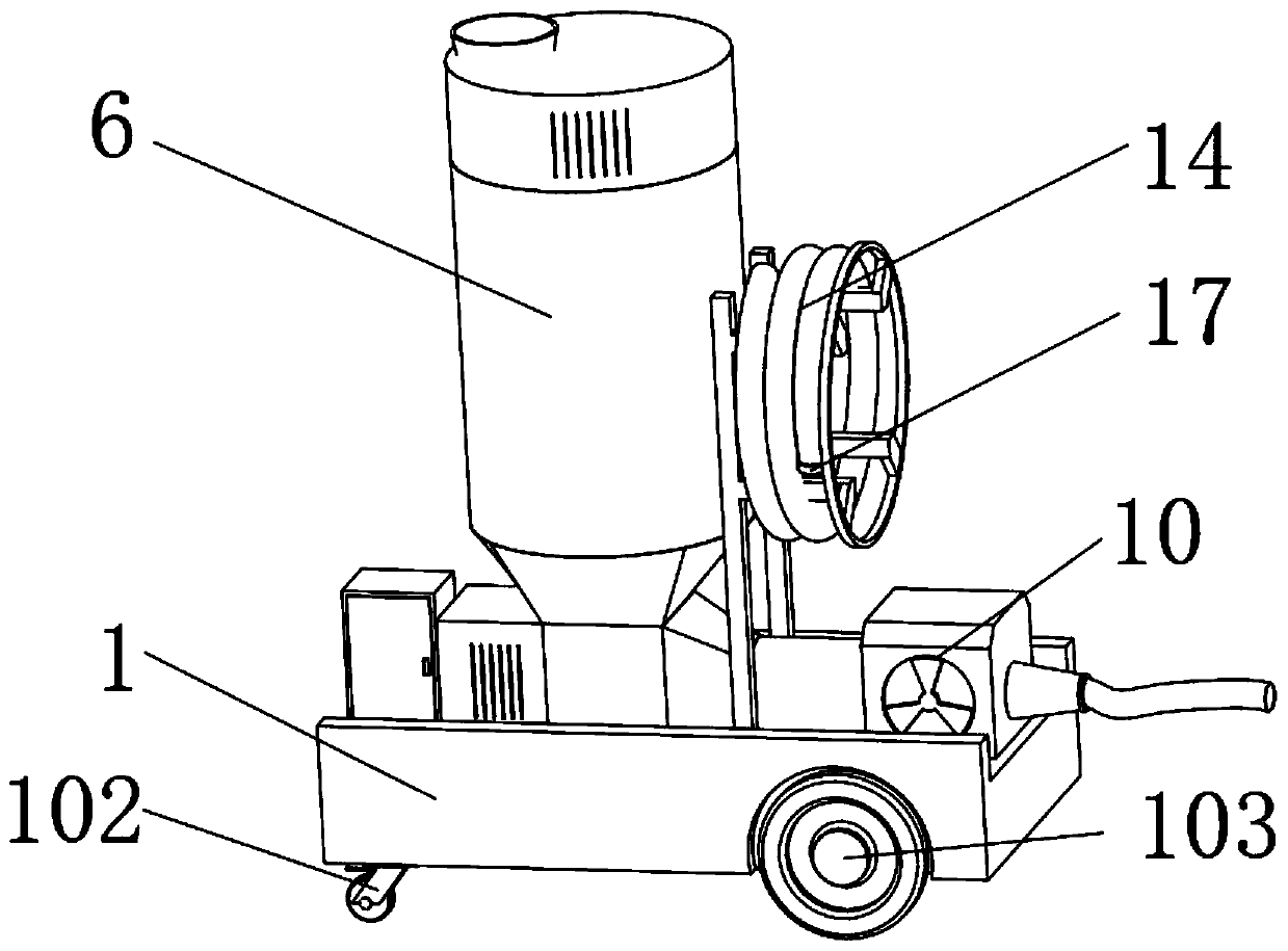
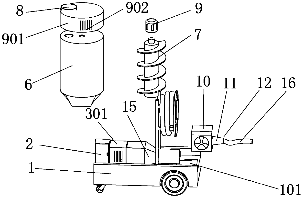
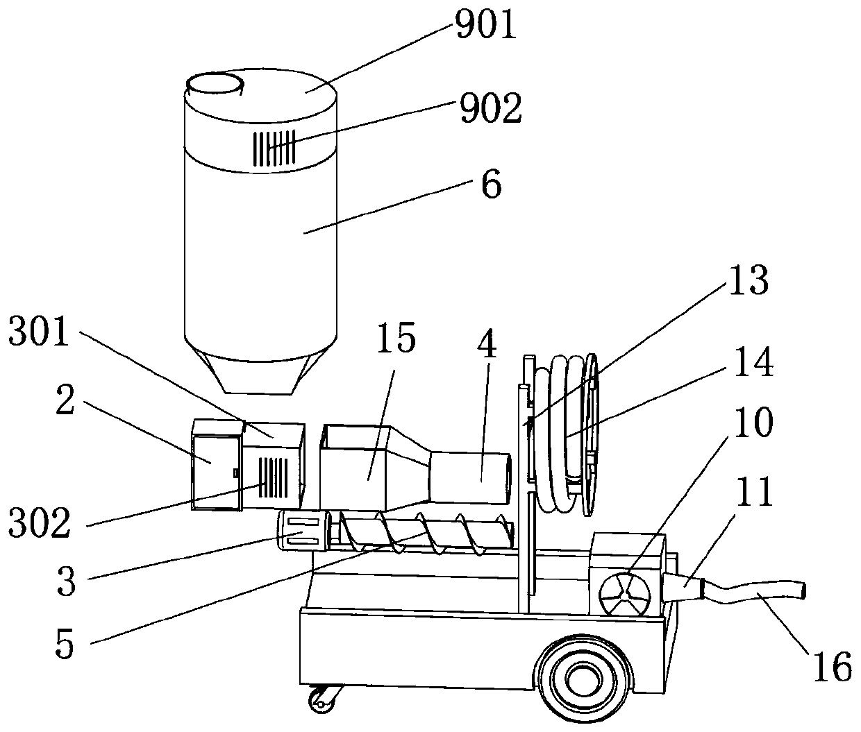
Examples


Embodiment Construction

[0022] The following will clearly and completely describe the technical solutions in the embodiments of the present invention with reference to the accompanying drawings in the embodiments of the present invention. Obviously, the described embodiments are only some, not all, embodiments of the present invention. All other embodiments obtained by persons of ordinary skill in the art based on the embodiments of the present invention belong to the protection scope of the present invention.

[0023] According to an embodiment of the present invention, a high-efficiency concrete pouring machine is provided.

[0024] Such as Figure 1-4 As shown, the concrete pouring machine according to the embodiment of the present invention includes a car body 1, a control cabinet 2 is arranged on the top side of the car body 1, and a motor 2 is arranged on the side of the control cabinet 2 close to the middle of the car body 1. 3. The output end of the motor 2 3 is provided with a horizontal st...


PUM


Abstract

The invention discloses an efficient concrete pouring machine and relates to the technical field of plastic processing. The efficient concrete pouring machine comprises a trolley body, one side of thetop of the trolley body is provided with a control cabinet, the side, close to the middle portion of the trolley body, of the control cabinet is provided with a second motor, the output end of the second motor is provided with a horizontal stirring tank, one inner cavity of the horizontal stirring tank is provided with a horizontal threaded rod, the top of the side, close to the second motor, ofthe horizontal stirring tank is provided with a vertical stirring tank, one inner cavity of the vertical stirring tank is provided with a vertical threaded rod, the top of the vertical stirring tank is fixedly provided with a material feeding hopper and a first motor, the side, away from the second motor, of the horizontal stirring tank is provided with a concrete pump, the other side of the concrete pump is provided with a material outlet pipe, and the other side of the material outlet pipe is provided with a hose clamping buckle. The efficient concrete pouring machine has the beneficial effects that under pressurizing of the concrete pump and pushing of the horizontal threaded rod, the pouring lifting range is increased, occurrence of the material outlet blockage phenomenon is avoided, and the course of pouring construction is guaranteed.

Description

technical field [0001] The invention relates to the technical field of plastic processing, in particular to a high-efficiency concrete pouring machine. Background technique [0002] Most modern buildings are reinforced concrete structures. This structure has the advantages of firmness, durability, good fire resistance, and low cost. In the process of pouring concrete, a concrete pouring machine is used. The pouring machine is mainly used for pressing The slurry, cement, quicklime, gypsum and aluminum powder paste suspension injected into the tank in a certain proportion are stirred to make them evenly mixed and fully reacted, and the mixed slurry is injected into the mold frame in time. The concrete pouring machine of the prior art Generally, the piston propeller is used to push the concrete slurry to the pump pipe. Since the propulsion mechanism adopts a reciprocating action mode, the delivery of the slurry is not stable enough, the pouring head is not high, and most of the...

Claims


Application Information

Patent Timeline
IPC IPC(8): E04G21/02E02D15/02
CPCE02D15/02E04G21/02
Inventor 赵爱红
Owner 合肥市日月新型材料有限公司
Learn More