
Electronic hydraulic brake

A hydraulic brake, electronic technology, applied in the direction of brake, brake transmission, foot start device, etc., can solve the problems of inability to perform emergency braking, lack of booster vacuum source, lack of conditions, etc., to shorten the longitudinal direction. Layout space, shortening response time of pressure buildup, and reducing the effect of shell stress

Active Publication Date: 2020-05-12
开沃新能源汽车集团股份有限公司
View PDF5 Cites 2 Cited by
  • Summary
  • Abstract
  • Description
  • Claims
  • Application Information

AI Technical Summary

Problems solved by technology

1. The power output no longer depends on the engine, so the vacuum source of the booster is also lacking. It is necessary to add an electric vacuum pump as a vacuum source, but the durability of the electric vacuum pump is difficult to meet the requirements of automobile braking, and it will increase the cost. The new type Brake development becomes extremely urgent
2. New energy vehicles are becoming more and more intelligent. In an emergency, the vehicle needs to communicate with the braking system, requiring the braking system to complete braking by itself. However, the vacuum booster is a purely mechanical structure and does not have the ability to communicate with the entire vehicle. conditions, emergency braking conditions cannot be performed
In addition, during the braking process of the car, the power of the car is lost through the heat generated by the friction between the wheel brake disc and the friction plate, resulting in a very serious energy loss. The traditional vacuum booster is limited by its structure and cannot change its braking energy. Consumption, in order to reduce losses, it is necessary to develop a new type of electronic hydraulic brake

Method used


Image

  • Electronic hydraulic brake
  • Electronic hydraulic brake

Examples


Embodiment Construction

[0016] The present invention will be further described below in conjunction with the accompanying drawings.

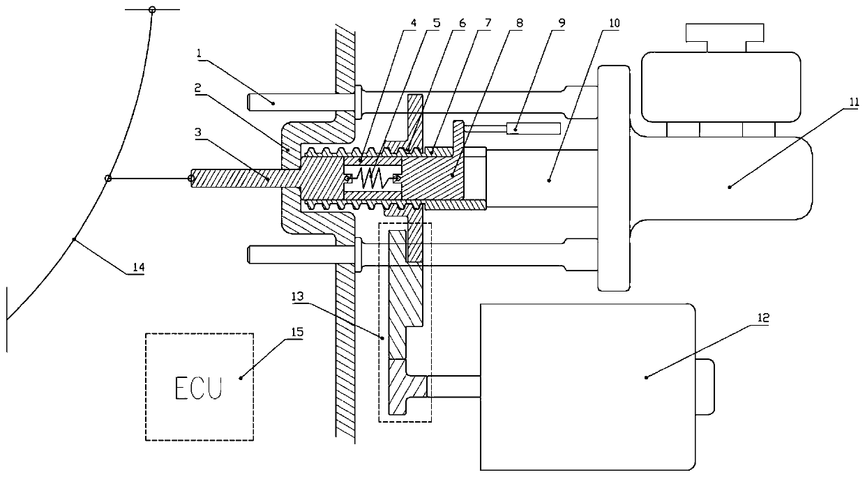
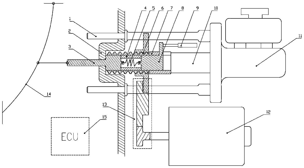
[0017] The electronic hydraulic brake of the present invention includes a through rod 1, a housing 2, a push rod 3, a sleeve 4, an elastic element 5, a gear nut 6, a screw 7, a slider 8, a displacement sensor 9, a master cylinder piston 10, and a motor 12 , gear set 13, pedal 14 and ECU15, wherein one end of the through rod 1 passes through the housing 2 and is fixed at the installation position, and the other end is fixed with the master cylinder 11, and the through rod 1 can transmit the thrust of the master cylinder piston 10. One end of the push rod 3 is connected to the pedal 14 , and the other end is connected to the elastic element 5 . The push rod 3 is closely attached to the sleeve 4 . The sleeve 4 can slide in the screw rod 7 , one end is close to the push rod 3 , and the other end is close to the slider 8 , so as to transmit the thrust from the push rod 3 to...


PUM


Abstract

The invention relates to an electronic hydraulic brake comprising a penetrating rod, a shell, a push rod, a sleeve, an elastic element, a gear nut, a lead screw, a sliding block, a displacement sensor, a main cylinder piston, a main cylinder, a motor, a gear set, a pedal and an ECU. The penetrating rod passes through the shell and then is fixed to the main cylinder. The push rod connects the pedaland the elastic element; the push rod and the sleeve slide in the screw rod; the sleeve clings to the push rod and the slide block; the elastic element is connected with the push rod and the slidingblock; the outer ring of the lead screw is meshed with the gear nut; the sliding block is connected with the elastic element and the displacement sensor; the sliding block and the main cylinder pistonare spaced; the displacement sensor is fixed to the shell and one end of the displacement sensor is attached to the sliding block; the main cylinder is fixedly connected with the penetrating rod; themotor is fixed to the shell, one end of the motor is connected with the gear set, the gear set is fixed to the shell, and the pedal is connected with the push rod.The ECU receives signals of the displacement sensor and controls the motor to act. With the combination mode of the gear set and the lead screw nut, the structural space is saved, and the transmission gap is reduced.

Description

Technical field: [0001] The invention belongs to the technical field of new energy vehicles, and relates to braking technology of new energy vehicles, in particular to an electronic hydraulic brake. Background technique: [0002] In the major systems of automobiles, the brake is a very critical component, and its performance will directly affect people's travel safety. In order to improve the comfort of the driver, domestic and foreign automobile companies widely use vacuum booster as the brake booster system of the car. The normal air pressure on the side produces a pressure difference, and then uses the pressure difference to strengthen the braking thrust, so as to achieve the purpose of reducing the burden on the driver. [0003] Due to environmental pollution and energy crisis, there has been an upsurge in the research and development of new energy vehicles worldwide. Compared with traditional fuel vehicles, new energy vehicles have several obvious characteristics, espe...

Claims


Application Information

Patent Timeline
IPC IPC(8): B60T7/04B60T13/74
CPCB60T7/04B60T13/745
Inventor 马跃龙周岩黄斌仲文诗黄永阔赵峯王文露张鑫尤振军谢宁刘立军
Owner 开沃新能源汽车集团股份有限公司
Learn More