
An intelligent numerical control stepless control bending machine with improved structure

A bending machine, intelligent technology, applied in the direction of forming tools, metal processing equipment, manufacturing tools, etc., can solve the problems of affecting efficiency, affecting the service life, increasing the cost of equipment use, etc., to improve the service life, effectively install and fix, and control the use. cost effect

Active Publication Date: 2021-09-07
NINGBO CHANGYANG MACHINERY IND CO LTD
View PDF10 Cites 0 Cited by
  • Summary
  • Abstract
  • Description
  • Claims
  • Application Information

AI Technical Summary

Problems solved by technology

[0003] However, when the lower formwork in the prior art is installed, the clamping block is mostly displaced by the clamping cylinder, and the clamping base is used to forcibly squeeze the lower formwork, so as to realize the installation and fixation of the lower formwork, although the lower formwork It is made of nylon material with a certain rebound rate, but when the clamping cylinder is too tight, although the installation of the lower formwork is relatively stable, but the lower formwork is in the middle section between each clamping cylinder, it will be in the lower formwork It is forced to stretch during bending processing. Even if the stretching deformation is small, it will seriously affect the service life of the lower template during continuous processing. When the clamping cylinder is too loose, although it can effectively avoid the lower template However, this will cause the lower template to be displaced relative to the clamping top block due to the influence of extrusion and bending during the bending process, and when it is reset after the bending is completed, it will lose the limit of extrusion, so that it cannot It is easy to reset, and it will be forced to squeeze and shrink during the next bending and extrusion process, which will also seriously affect its service life, and then the lower template needs to be replaced frequently, which increases the use cost of the equipment, and the frequent disassembly process It will also greatly affect the efficiency of normal production and processing. For this reason, we propose an intelligent numerical control stepless control bending machine with improved structure

Method used


Image

  • An intelligent numerical control stepless control bending machine with improved structure
  • An intelligent numerical control stepless control bending machine with improved structure
  • An intelligent numerical control stepless control bending machine with improved structure

Examples


Embodiment 1

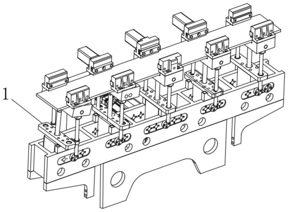
[0032] see Figure 3-5 , the present invention provides a technical solution: an intelligent digital control stepless control bending machine with an improved structure, including a pneumatic lifting base 1, which is the lower template installation structure inside the stepless control bending machine in the prior art , I won’t go into too much detail here;

[0033] The top of the pneumatic lifting base 1 is equidistantly equipped with a plurality of lower mold clamping mechanisms 2 that can be rolled and connected with the lower template, and both ends of the top of the pneumatic lifting base 1 are provided with end restraints that can be rolled and connected with the lower template. The position mechanism 3 is different from the prior art through the lower mold clamping mechanism 2 and the end limit mechanism 3 that can be rolled and connected with the lower formwork, and ensures that the lower formwork is effectively installed and fixed. During the processing, it can effec...

Embodiment 2

[0038] see Figure 6-7 , the present invention provides an optimized technical solution of Embodiment 1: the limit base 10 includes a fixed seat 13 and a cover plate 14, the fixed seat 13 is fixed at the end of the pneumatic lifting base 1, and the top of the fixed seat 13 The side close to the clamping mechanism 2 of the lower mold is provided with an insertion groove 15, the insertion groove 15 has a strip-shaped groove structure, and a plurality of the balls 12 are respectively provided with inner walls on both sides of the insertion groove 15, and the cover plate 14 is movable. Installed on the top of the fixing seat 13, and the cover plate 14 is also provided with a curved joint groove 7 communicating with the insertion groove 15. The insertion groove 15 and the curved joint groove 7 together form the insertion limit groove 11. When in use , after the lower template is fixed by the lower mold clamping mechanism 2, press its end into the insertion groove 15 in the fixing s...

Embodiment 3

[0041] see Figure 8-13 , the present invention provides an optimized technical solution of Embodiment 2: clips 17 are provided on both sides of the top of the fixing seat 13, and the fixing seat 13 is movably connected to the cover plate 14 through the clips 17, and the clips 17, while ensuring that the cover plate 14 and the fixing seat 13 are effectively fixed, it further facilitates the disassembly and fixing work of the cover plate 14 and the fixing seat 13, thereby further facilitating the fixing and limiting work of the end of the lower formwork .

[0042] The snap-in piece 17 includes a snap-in block 18, the snap-in block 18 is preferably a polygonal cylinder structure but not limited, the snap-in block 18 is fixed on the top of the fixing seat 13, and both sides of the cover plate 14 are provided with There is a through snap-in slot 19, the snap-in slot 19 is adapted to the structure of the snap-in block 18, and the snap-in block 18 is respectively fitted with the sn...


PUM


Abstract

The invention discloses an intelligent numerical control stepless control bending machine with an improved structure, which includes a pneumatic lifting base, and the top of the pneumatic lifting base is equidistantly equipped with a plurality of lower mold clamping mechanisms that can be rolled and connected with the lower template, and Both ends of the top of the pneumatic lifting base are equipped with end limit mechanisms that can be rolled and connected with the lower formwork. The intelligent numerical control stepless control bending machine with this improved structure is different from the existing technology and ensures effective installation and fixation of the lower formwork. At the same time, during the bending process of the aluminum guide rail of the automobile sunroof, it can effectively avoid the situation that the lower template is forcibly stretched or squeezed, thereby effectively improving the service life of the lower template, thereby effectively controlling the cost of equipment and equipment, and avoiding frequent Disassembly and assembly will affect the efficiency of normal production and processing.

Description

technical field [0001] The invention relates to the technical field of bending and forming devices for metal profiles, in particular to an intelligent numerical control stepless control bending machine with an improved structure. Background technique [0002] At present, metal profiles with a certain amount of bending are widely used in production and life, especially in the manufacture of aircraft and automobiles. In order to obtain metal profiles with a predetermined amount of bending, it is necessary to bend the metal profiles For example, the aluminum material applied to the guide rail of the automobile sunroof needs to be bent and formed during processing. When the bending equipment for the aluminum guide rail of the automobile sunroof in the prior art is used in work, most of the workpieces are directly placed on the lower mold of the bending equipment. On, and through the press fit of the upper mold to complete the bending, and in the bending process, the lower mold b...

Claims


Application Information

Patent Timeline
Patent Type & Authority Patents(China)
IPC IPC(8): B21D7/00B21D37/04B21D7/12
CPCB21D7/00B21D7/12B21D37/04
Inventor 孔燕成夏立法郭德仓
Owner NINGBO CHANGYANG MACHINERY IND CO LTD
Learn More