Machine room inspection robot

An inspection robot and robot technology, applied in the field of robots, can solve the problems of easy collision with cabinets, small monitoring range, inflexibility, etc., to avoid damage and increase the monitoring range.

Pending Publication Date: 2020-05-08
天津市远畅科技有限公司
View PDF0 Cites 1 Cited by
  • Summary
  • Abstract
  • Description
  • Claims
  • Application Information

AI Technical Summary

Problems solved by technology

[0003] In order to ensure the normal operation of the business, it is necessary to monitor the physical environment and equipment status in the computer room, such as the temperature in the computer room, the signal status light of the equipment, the operation status light of the equipment, etc. If the above targets are not monitored in time, once a problem occurs It is easy to cause losses. The existing computer room inspection is usually completed by the computer room walking inspection robot. It is found in use that because it can only shuttle and walk on the ground for inspection, the monitoring range is small and the moving range is limited. However, if drones are used for inspections, because they are at a certain height from the ground after flying, when the staff is walking in the computer room, they are easy to touch the propeller of the drone by mistake, causing injury , and the UAV is easy to collide with the cabinet when flying, resulting in damage to the UAV. Therefore, it is necessary to design a machine room inspection robot to solve the above problems

Method used


Image

  • Machine room inspection robot
  • Machine room inspection robot
  • Machine room inspection robot

Examples


Embodiment Construction

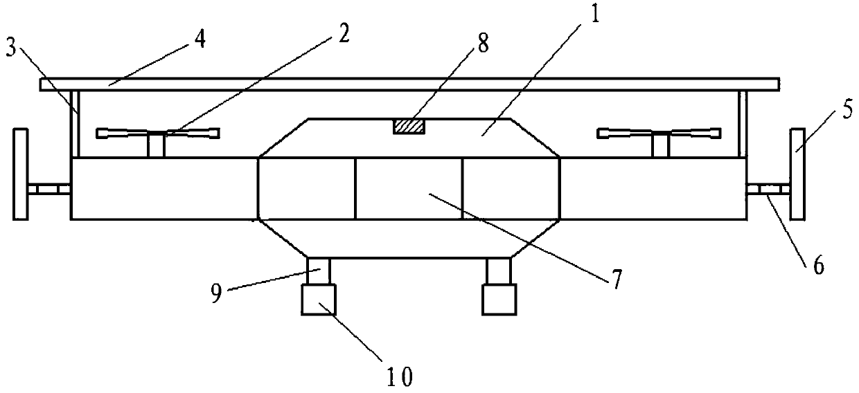
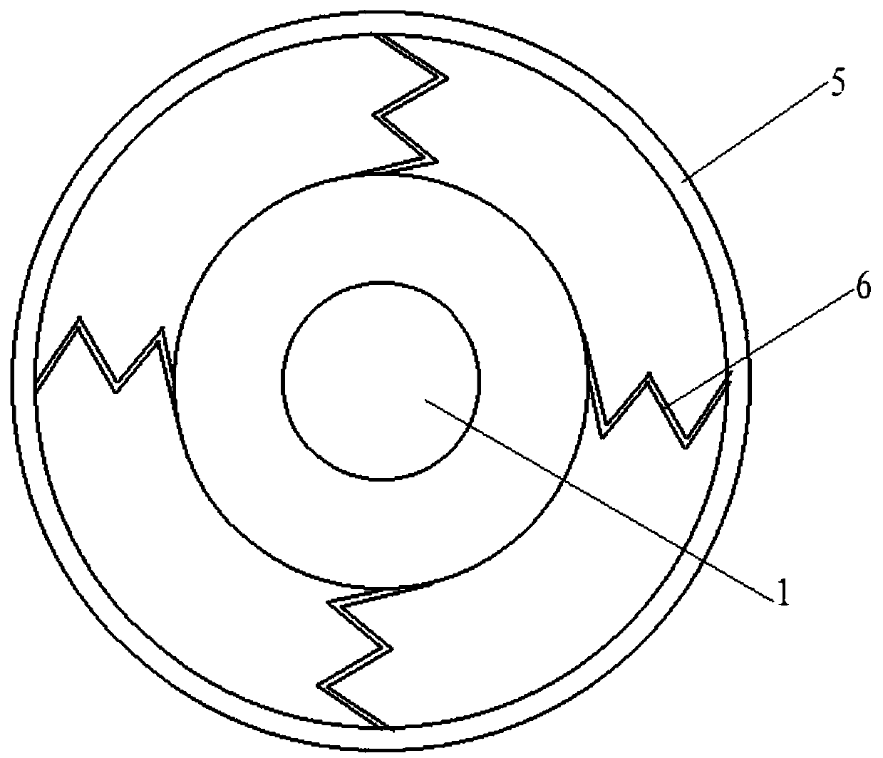
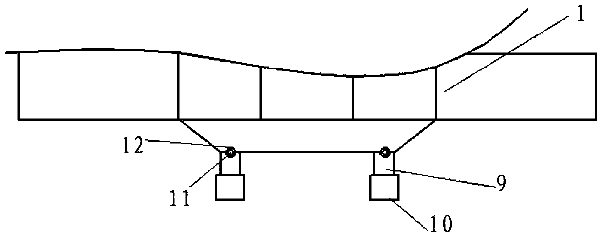
[0016] The present invention is further described below in conjunction with the accompanying drawings: the present invention is a machine room inspection robot, including a robot main body 1, a propeller 2, a support rod 3, a top protective plate 4, a protective ring 5, a shrapnel 6, and a control part 7 , distance sensor 8, connecting rod 9, road wheel 10, rotating shaft 11, described robot main body 1 is the unmanned aerial vehicle that is viewed as circular structure from above, and described robot main body 1 top two sides are respectively provided with propeller 2, and described robot main body The top of 1 is provided with a support rod 3, the top of the support rod 3 is provided with a top protective plate 4, and the outer periphery of the robot main body 1 is provided with a protective ring 5, and the protective ring 5 is connected to the robot main body 1 through a shrapnel 6, so The outer circumference of the top of the robot main body 1 is provided with a distance se...


PUM


Abstract

Provided is a machine room inspection robot, comprising a robot body, propellers, supporting rods, a top protection plate, a protection ring, elastic pieces, a control part, distance sensors, connecting rods, walking wheels and rotating shafts. The robot body is an unmanned aerial vehicle of a circular structure when overlooked. Propellers are respectively arranged on two sides of the top of the robot body. A supporting rod is arranged at the top of the robot body. A top protection plate is arranged at the tops of the supporting rods. A protective ring is arranged on the periphery of the robotbody. The protection ring is connected with the robot body through an elastic piece, a distance sensor is arranged on the periphery of the top of the robot body, a control part is arranged in the robot body, the distance sensor is electrically connected with the control part through a cable, connecting rods are symmetrically arranged at the bottom of the robot body relative to the center line, and walking wheels are arranged at the bottom ends of the connecting rods. The robot has the advantages that the inspection mode that a traditional inspection robot can only shuttle and walk on the ground for inspection is changed, the moving range of the robot is not limited by ground obstacles, and certain flexibility is achieved.

Description

technical field [0001] The invention relates to a robot, in particular to a computer room inspection robot. Background technique [0002] In the IT industry, a computer room generally refers to a place where servers are stored in telecommunications, Netcom, mobile, dual-line, electric power, government or enterprises, etc., and IT services are provided for users and employees. There are thousands of cabinets on a large tens of thousands of square meters, or even more. Various servers and minicomputers are usually placed in the computer room, such as IBM minicomputers, HP minicomputers, SUN minicomputers, etc. The temperature and humidity of the computer room There are strict requirements for anti-static measures, and non-professional project personnel are generally not allowed to enter. The servers in the computer room run many services, such as mobile multimedia messages, short messages, and call services. The computer room is very important. Without the computer room, wor...

Claims


Application Information

Patent Timeline
IPC IPC(8): G05D1/10
CPCG05D1/101
Inventor 郭爽卢岩康焱贾鹏
Owner 天津市远畅科技有限公司
Why Eureka
Try Eureka