Resistance adaptive ammunition belt device

A self-adaptive, elastic belt technology, applied in offensive equipment, weapon accessories, barrels, etc., can solve the problems of large motion acceleration, low projectile motion resistance, affecting the air-holding performance of the elastic belt, etc., to improve the launch performance, promote the borehole Internal combustion, the effect of increasing contact stress

Active Publication Date: 2020-05-08
NANJING UNIV OF SCI & TECH
View PDF7 Cites 0 Cited by
  • Summary
  • Abstract
  • Description
  • Claims
  • Application Information

AI Technical Summary

Problems solved by technology

This situation will bring negative effects in two aspects: one is that the projectile movement resistance caused by the belt is low, which will lead to a relatively large acceleration of the projectile’s motion at the initial stage, which will lead to insufficient combustion of the charge in the chamber; the second is the belt The fitting effect between the barrel and the barrel is not good, which in turn affects the air-holding performance of the elastic belt
The conventional elastic belt embedded in the barrel in advance cannot solve the negative effects of these two aspects

Method used


Image

  • Resistance adaptive ammunition belt device
  • Resistance adaptive ammunition belt device
  • Resistance adaptive ammunition belt device

Examples


Embodiment Construction

[0018] The present invention will be described in further detail below in conjunction with the accompanying drawings.

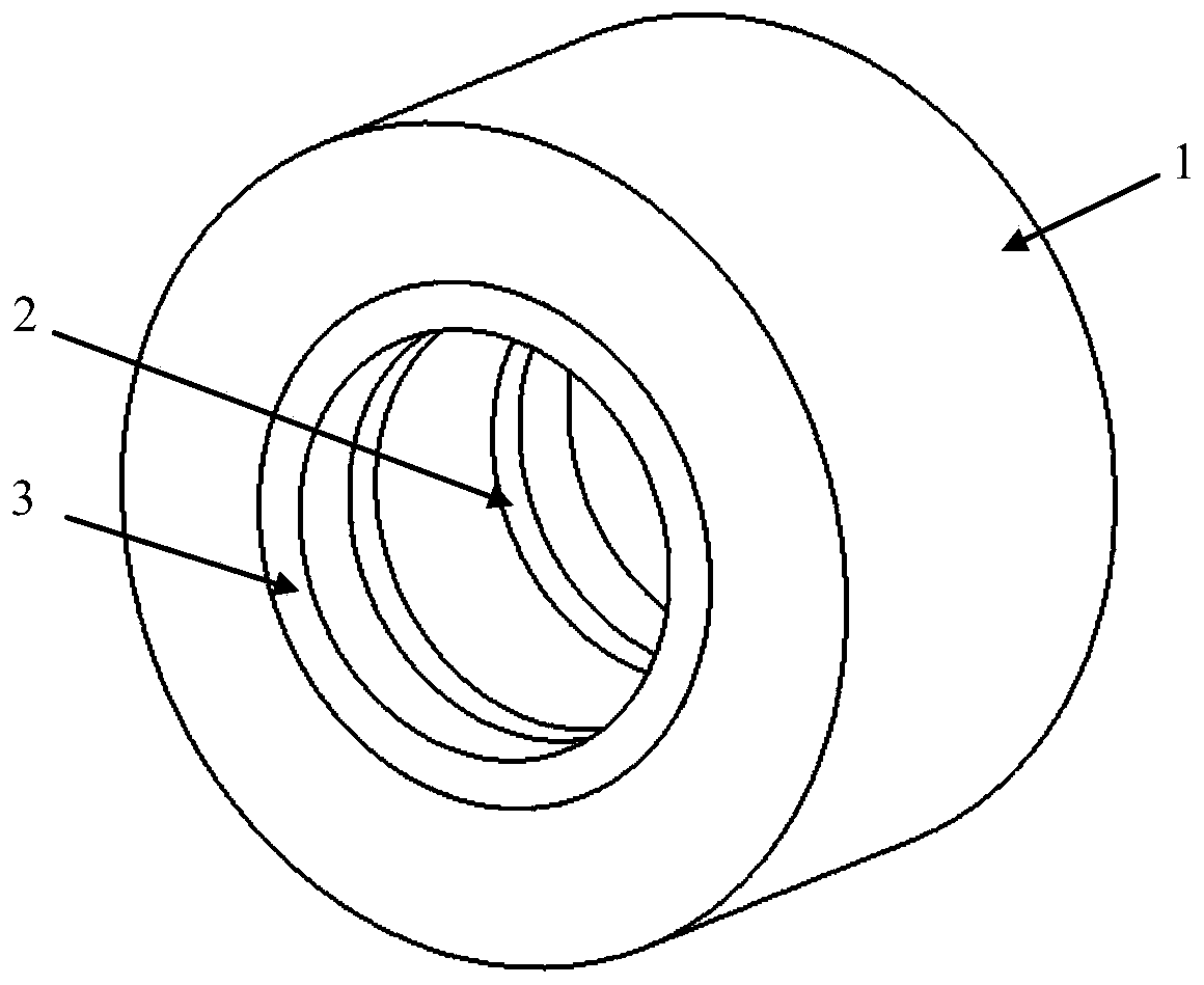
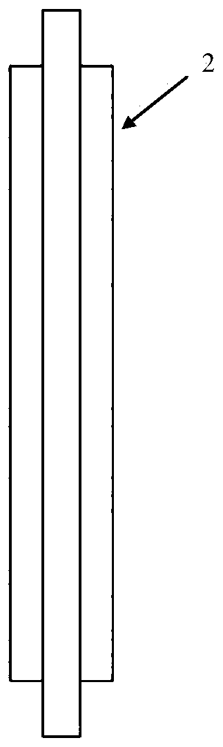
[0019] The invention proposes an elastic belt device for adaptively adjusting the movement resistance of projectiles, which includes an elastic belt main body including two rectangular grooves and a semicircular groove, and two elastic belt bottom brackets including rectangular bosses.

[0020] Such as Figure 1-5 As shown, the resistance adaptive elastic belt device includes an elastic belt main body 1, an elastic belt bottom bracket I2 and an elastic belt bottom bracket II3.

[0021] Limited radial relative sliding can occur between the elastic belt main body 1 and the elastic belt bottom support I2 and the elastic belt bottom support II3.

[0022] There is a T-shaped annular groove on the inner wall of the two end faces of the main body 1 of the belt, and there is a semicircular annular groove on the inner wall of the main body 1 of the belt, which is use...


PUM


Abstract

The invention belongs to the field of internal ballistics launching, and particularly relates to a resistance adaptive ammunition belt device. The resistance adaptive ammunition belt device comprisesan ammunition belt main body, an ammunition belt bottom holder I and an ammunition belt bottom holder II, the ammunition belt main body is wholly in a cylindrical shape, annular grooves with T-shapedcross-sections are formed in the two ends of the inner side surface of the ammunition belt main body correspondingly, and an annular groove with a semicircular section is formed in the middle of the inner side surface of the ammunition belt main body; the structures and the sizes of the ammunition belt bottom holder I and the ammunition belt bottom holder II are the same, annular protrusions are arranged on the peripheries of the ammunition belt bottom holder I and the ammunition belt bottom holder II, the annular protrusions are in clearance fit with the T-shaped annular grooves of the ammunition belt main body, and the outer side surfaces of the ammunition belt bottom holder I and the ammunition belt bottom holder II are located in the same plane as the outer side surface of the ammunition belt main body; and the ammunition belt main body, the ammunition belt bottom holder I, the ammunition belt bottom holder II and the outer surface of a projectile feeding belt groove form a semi-cylindrical closed cavity jointly. According to the resistance adaptive ammunition belt device, by changing the structure of the ammunition belt device, the system sealing performance and sufficient combustion of ammunition charging when a launcher embedded in a barrel in advance is launched are realized, and the launching performance of a whole launching system is directly improved.

Description

technical field [0001] The invention belongs to the field of internal ballistic launch, and in particular relates to a resistance self-adaptive elastic belt device. Background technique [0002] During the internal ballistic launch process, for projectiles that need to be embedded in the barrel in advance, the matching relationship between the belt and the barrel is generally a clearance fit. This situation will bring negative effects in two aspects: one is that the projectile movement resistance caused by the belt is low, which will lead to a relatively large acceleration of the projectile’s motion at the initial stage, which will lead to insufficient combustion of the charge in the chamber; the second is the belt The fitting effect between the barrel and the barrel is not good, which in turn affects the air-holding performance of the elastic belt. The conventional elastic belt embedded in the barrel in advance cannot solve the negative effects of these two aspects. Cont...

Claims


Application Information

Patent Timeline
IPC IPC(8): F41A21/18F41A35/00
CPCF41A21/18F41A35/00
Inventor 张小兵胡朝斌
Owner NANJING UNIV OF SCI & TECH
Why Eureka
Try Eureka