
Position adjusting device for cable conveyor for cable laying

A cable conveyor and cable laying technology, applied in the direction of supporting machines, mechanical equipment, machines/supports, etc., can solve the problem of unable to adjust the height of the conveyor smoothly, so as to improve the laying efficiency, reduce manpower and time-consuming, The effect of avoiding duplication of work and manpower consumption

Pending Publication Date: 2020-05-08
JINHUA POWER TRANSMISSION & DISTRIBUTION ENG
View PDF0 Cites 0 Cited by
  • Summary
  • Abstract
  • Description
  • Claims
  • Application Information

AI Technical Summary

Problems solved by technology

[0006] The height adjustment range of the railroad wood is fixed, and it is impossible to adjust the height of the conveyor smoothly. Usually, it is necessary to add other mats to complete the hole alignment

Method used


Image

  • Position adjusting device for cable conveyor for cable laying
  • Position adjusting device for cable conveyor for cable laying
  • Position adjusting device for cable conveyor for cable laying

Examples


Embodiment 1

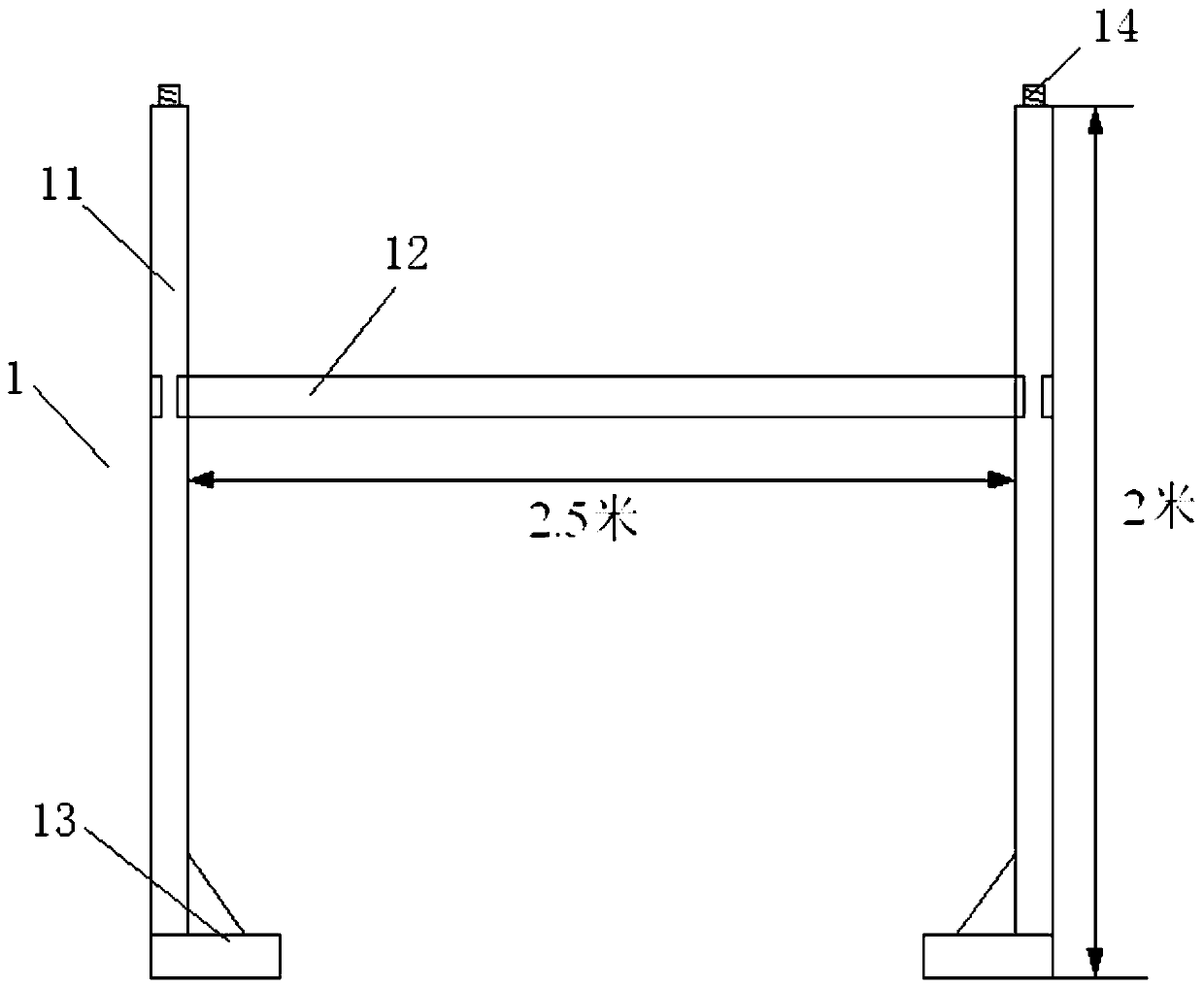
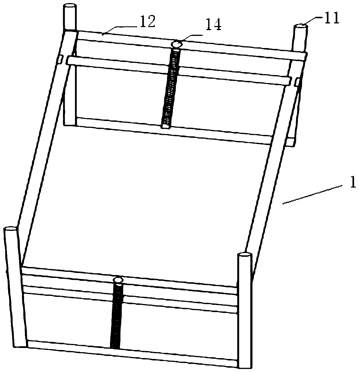
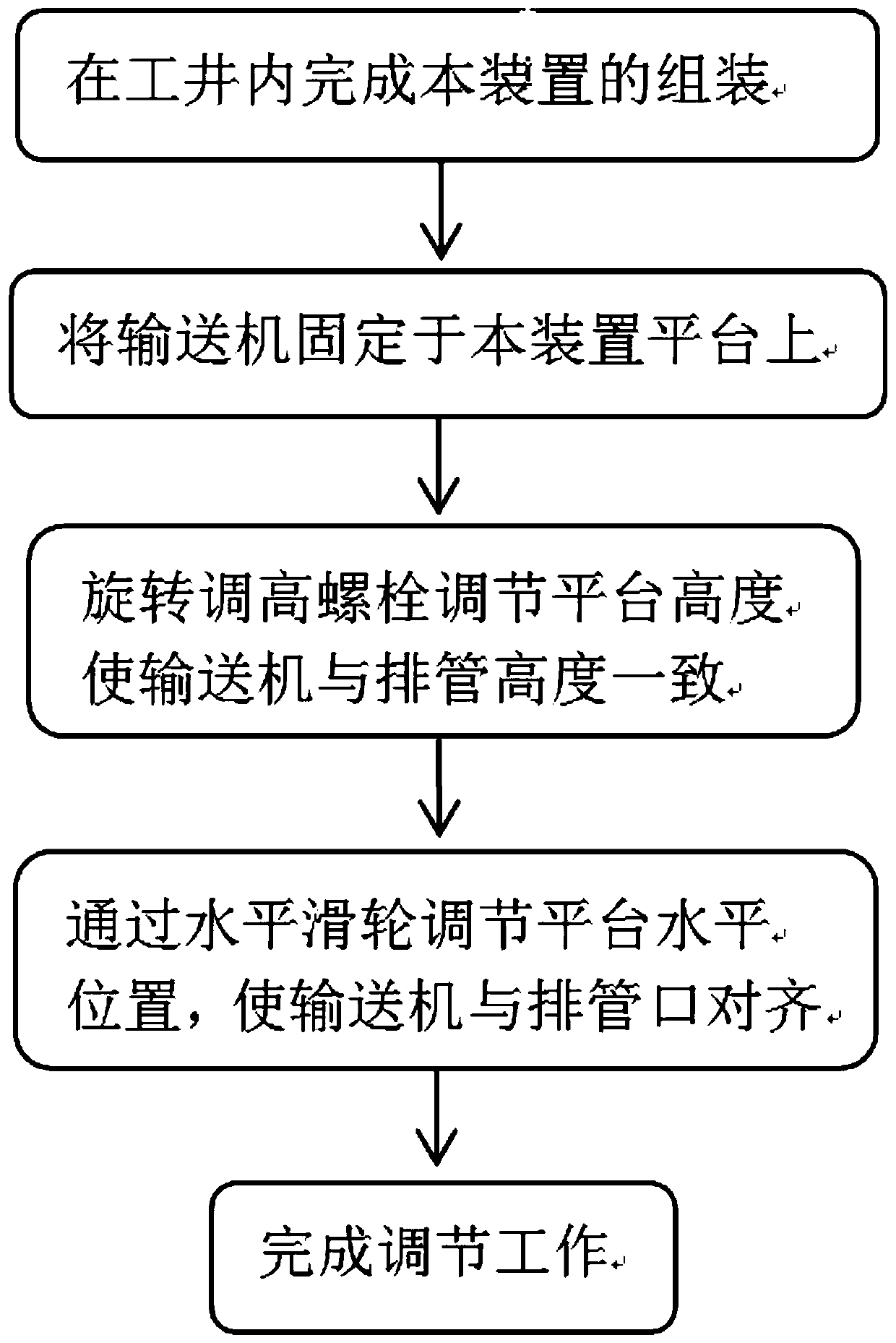
[0033] refer to Figure 1 to Figure 4 As shown, a cable conveyor position adjustment device for cable laying, which includes:

[0034] The mounting bracket 1 includes four uprights 11 arranged at the four corners of a rectangle, a mounting crossbeam 12 connecting two adjacent uprights, and the base of the cable conveyor is supported on the mounting crossbeam;

[0035] The lifting support 2 is fixed with the mounting bracket, so as to realize height adjustment together with the mounting bracket;

[0036] Chassis 3, with rollers 31, is used to realize the overall horizontal position movement of the device, so as to realize the horizontal position adjustment of the cable conveyor;

[0037] The height adjustment structure is used to drive the lifting support up and down, thereby driving the installation bracket up and down, and realizing the height adjustment of the cable conveyor.

[0038] Specifically, the column 11 is made of galvanized steel pipe, and the installation beam 1...

Embodiment 2

[0044] The difference from Embodiment 1 is that, in order to realize automatic adjustment, the height adjustment structure is a hydraulic cylinder 21, and the hydraulic cylinder includes a cylinder body provided with a piston chamber, a piston is arranged in the piston chamber, and the piston is installed It is connected with the piston rod, and the piston rod is connected with the lifting support.

[0045] Wherein, an oil inlet hole is opened on the cylinder block of the oil cylinder, and an oil inlet pipeline is connected to the oil inlet hole, and a solenoid valve for controlling hydraulic oil to enter the piston cavity is arranged on the oil inlet pipeline.

[0046] The hydraulic cylinder 21 is arranged below the central position of the lifting support, and guide sleeves are connected at least at the center positions of both sides of the lifting support. The guide sleeve cooperates with the guide rod 22, and the guide rod is fixed on the chassis.


PUM


Abstract

The invention discloses a position adjusting device for a cable conveyor for cable laying. The position adjusting device comprises a mounting bracket, a lifting supporting seat, a chassis and a heightadjusting structure; the mounting bracket comprises four vertical columns arranged on the four rectangular corners and mounting transverse beams connecting every two adjacent vertical columns, and abase of the cable conveyor is supported on the mounting transverse beams; the lifting supporting seat and the mounting bracket are fixed, and thus height adjusting is achieved through the lifting supporting seat and the mounting bracket together; the chassis is provided with idler wheels and used for realizing overall horizontal position moving of the position adjusting device, and thus horizontalposition adjusting of the cable conveyor is achieved; and the height adjusting structure is used for driving the lifting supporting seat to ascend and descend, thus the mounting bracket is driven toascend and descend, and height adjusting of the cable conveyor is achieved. According to the position adjusting device, unnecessary repeated work and labor consumption of the position adjusting link of the cable laying conveyor are effectively avoided, labor required by adjusting work is greatly lowered, the consumed time required by the adjusting work is greatly shortened, and the cable duct banklaying efficiency can be improved well.

Description

technical field [0001] The invention belongs to the technical field of electric power construction, and in particular relates to a construction device for laying cables by using a cable conveyor. Background technique [0002] The cable laying method of the cable conveyor can effectively reduce the traction force and lateral pressure on the cable body during the laying process, so as to better ensure the laying quality. Therefore, this method has replaced the human and mechanical traction laying method and has become the most commonly used cable at this stage. laying method. [0003] When using conveyors to lay high-voltage cables, it is necessary to arrange cable conveyors in the wells of the whole line, and the position of the conveyors needs to be adjusted after each phase of cable is laid. Adjusting the position of the conveyor according to the traditional method has the following disadvantages: [0004] The traditional method uses padded railroad wood to adjust the con...

Claims


Application Information

Patent Timeline
Patent Type & Authority Applications(China)
IPC IPC(8): F16M11/24F16M11/18F16M11/42
CPCF16M11/24F16M11/18F16M11/42F16M2200/08
Inventor 张航汤春俊李策策徐志勇许剑毛水强胡宏峰葛健玮黄俊鹏刘田野蔡成立马锦涛
Owner JINHUA POWER TRANSMISSION & DISTRIBUTION ENG
Learn More