
A buffer device for transmission

A buffer device and transmission technology, applied in clutches, friction clutches, springs/shock absorbers, etc., can solve the problems of transmission power output shaft impact, damage to the internal structure of the transmission, and a large speed gap between the clutch disc and the friction disc.

Active Publication Date: 2021-09-21
福建中维动力科技股份有限公司
View PDF6 Cites 0 Cited by
  • Summary
  • Abstract
  • Description
  • Claims
  • Application Information

AI Technical Summary

Problems solved by technology

[0002] When the vehicle shifts gears, the clutch plate and friction disc in the transmission generally need to be separated first, and then fit together after the gear shift is completed. Since the clutch plate is directly connected to the power input shaft of the engine, the friction disc is directly connected to the power output shaft of the transmission. Therefore, the speed difference between the clutch disc and the friction disc is relatively large, and the moment the two are attached together will cause an impact on the power output shaft of the transmission, which may cause damage to the internal structure of the transmission after long-term use

Method used


Image

  • A buffer device for transmission
  • A buffer device for transmission
  • A buffer device for transmission

Examples


Embodiment 1

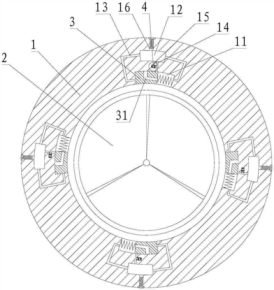
[0040] A buffer device for a transmission, comprising an outer ring 1 and a friction disc 2;

[0041] The friction disc 2 is located in the middle of the outer ring 1, and four buffer blocks 3 are uniformly arranged on the edge of the friction disc 2;

[0042] A buffer chamber 11 corresponding to the buffer block 3 is provided in the outer ring 1, the buffer block 3 is slidably connected in the buffer chamber 11, and one end of the buffer block 3 is elastically connected to the inner wall of the buffer chamber 11 through a spring;

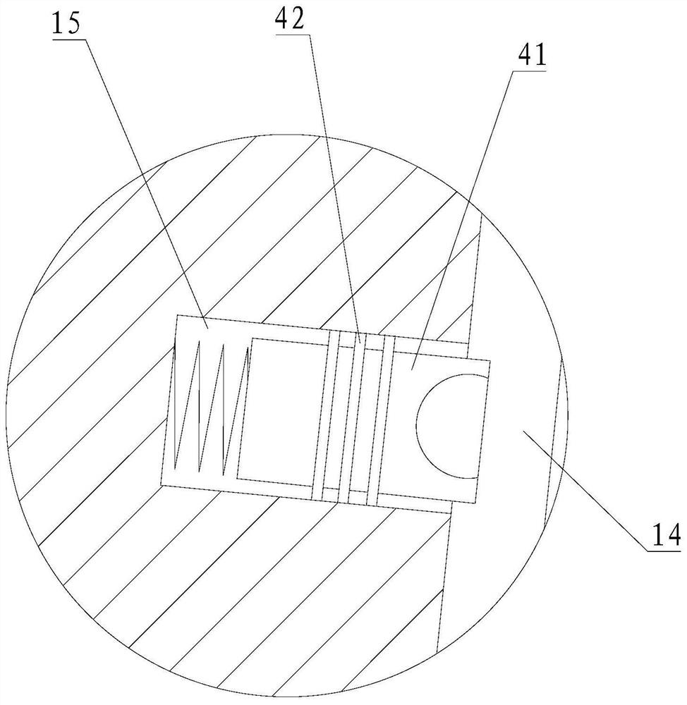
[0043] The inside of the outer ring 1 is also provided with an oil chamber 12 corresponding to the buffer chamber 11. Both ends of the oil chamber 12 communicate with the two ends of the buffer chamber 11 through the first hole 13. There is also a second channel 14 between them, and an oil injection hole 16 is opened on the outer ring 1, and the oil injection hole 16 communicates with the oil chamber 12, and a sealing bolt is arranged in the oil in...


PUM


Abstract

The invention relates to the field of transmissions, in particular to a buffer device for a transmission, comprising an outer ring and a friction disc; the friction disc is located in the middle of the outer ring, and a plurality of buffer blocks are uniformly arranged on the edge of the friction disc; There is a buffer cavity corresponding to the buffer block in the outer ring, the buffer block is slidably connected in the buffer cavity, and one end of the buffer block is elastically connected to the inner wall of the buffer cavity through a spring; there is also a buffer cavity inside the outer ring. The oil chamber corresponding to the cavity, the two ends of the oil chamber communicate with the two ends of the buffer chamber through the first hole, and there is also a second hole between the buffer chamber and the oil chamber; the beneficial effect of the present invention is that: when the clutch plate and When the friction disc is attached, the hydraulic oil can flow in the buffer chamber and the oil chamber to play a buffer effect between the friction disc and the outer ring. The second hole and the third hole play a role of pressure relief to prevent the clutch plate At the moment of fitting with the friction disc, the pressure of the hydraulic oil rises sharply, resulting in damage to the outer ring.

Description

technical field [0001] The invention relates to the field of transmissions, in particular to a buffer device for a transmission. Background technique [0002] When the vehicle shifts gears, the clutch plate and friction disc in the transmission generally need to be separated first, and then fit together after the gear shift is completed. Since the clutch plate is directly connected to the power input shaft of the engine, the friction disc is directly connected to the power output shaft of the transmission. Therefore, the speed gap between the clutch plate and the friction disc is relatively large, and the moment the two are attached will cause an impact on the power output shaft of the transmission, and may cause damage to the internal structure of the transmission after long-term use. Contents of the invention [0003] The technical problem to be solved by the present invention is to provide a buffering device for a transmission which can avoid the shock caused to the tra...

Claims


Application Information

Patent Timeline
Patent Type & Authority Patents(China)
IPC IPC(8): F16D13/58F16F15/16
CPCF16D13/58F16F15/161F16F15/162F16F15/165
Inventor 薛天宝罗天生周荣斌雷作钊
Owner 福建中维动力科技股份有限公司
Learn More