
Efficient metal plate stamping equipment

A stamping equipment and sheet metal technology, which is applied in the field of high-efficiency sheet metal stamping equipment, can solve the problems of low production efficiency, unstable product quality, and high processing costs of stamping equipment, so as to improve production efficiency, reduce labor intensity, production costs, and quality The effect of strong stability

Active Publication Date: 2020-05-08
SIASUN ROBOT & AUTOMATION LIMITED BY SHARE
View PDF9 Cites 1 Cited by
  • Summary
  • Abstract
  • Description
  • Claims
  • Application Information

AI Technical Summary

Problems solved by technology

[0005] In order to overcome the technical problems of low production efficiency, easy mistakes in the processing process, unstable product quality and high processing cost in the prior art of stamping equipment that uses multiple molds and divides multiple processes to complete product stamping, the present invention provides a A high-efficiency sheet metal stamping equipment, which can be adapted to the same process of automatic positioning and clamping of multi-model and multi-standard sheet metal products with various hole types, multi-size and specification holes, and different hole spacing, and can realize simultaneous rapid punching of multiple holes and online Automatic detection, high product quality and strong quality stability, in addition, the stamping equipment improves production efficiency and effectively reduces labor intensity and production costs

Method used


Image

  • Efficient metal plate stamping equipment
  • Efficient metal plate stamping equipment
  • Efficient metal plate stamping equipment

Examples


Embodiment

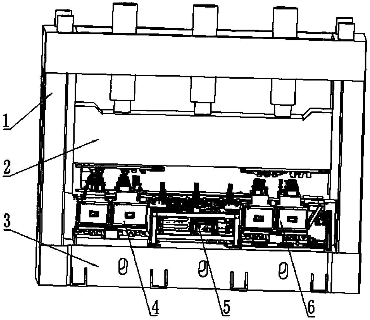
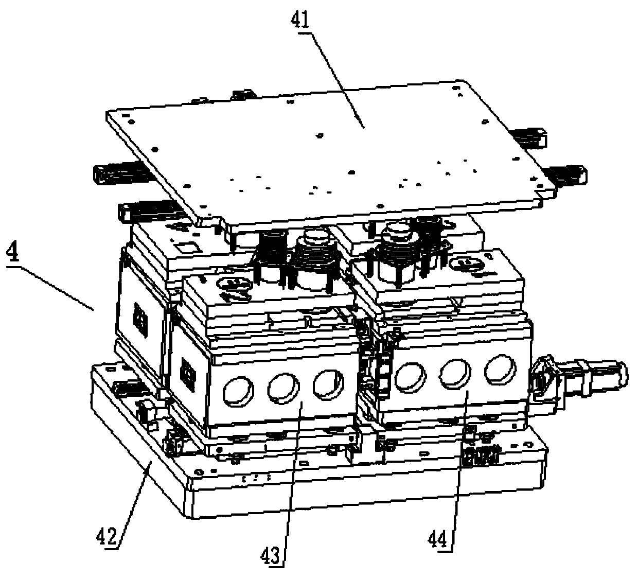
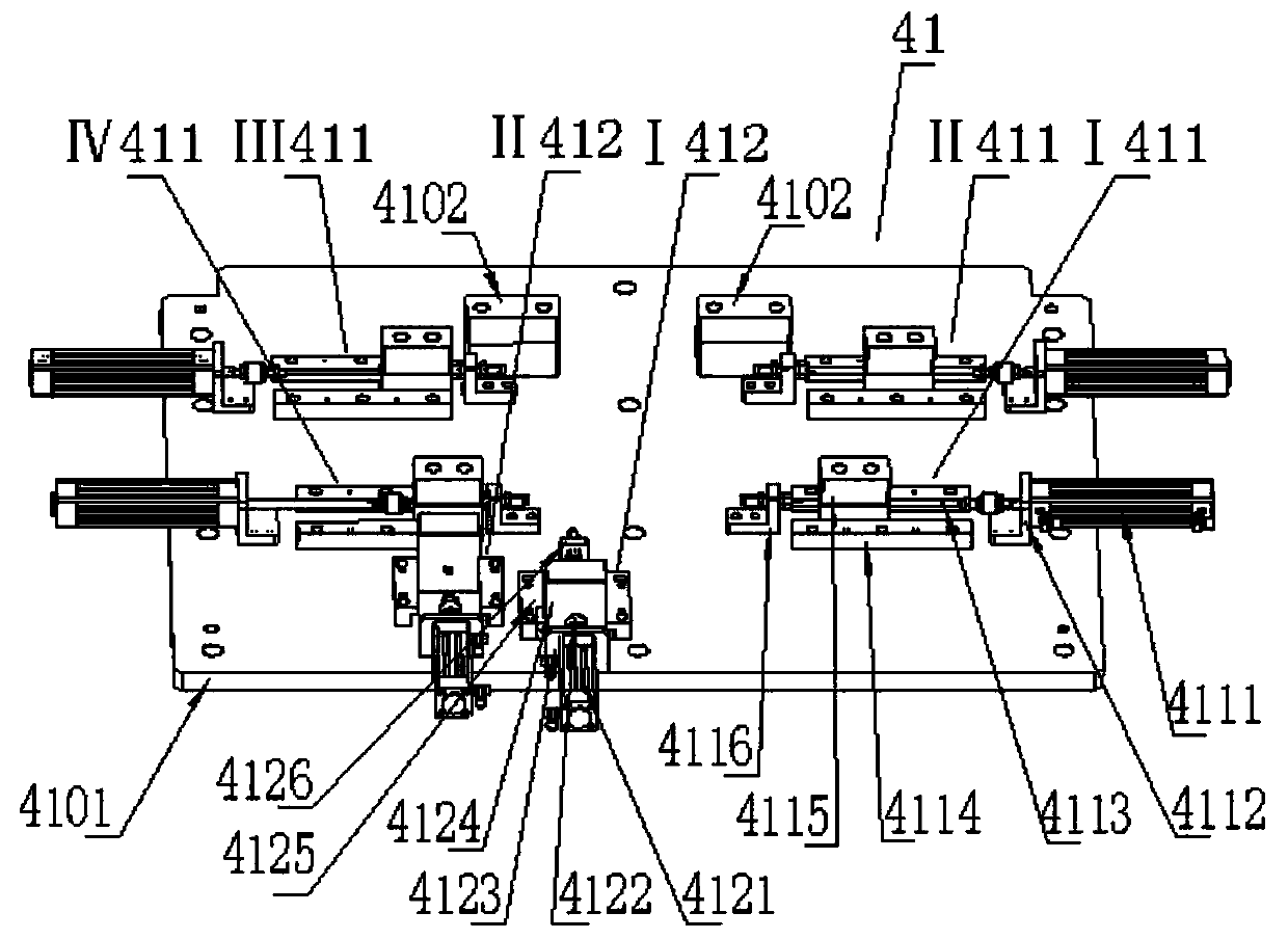
[0039] Such as Figure 1 to Figure 18As shown, a high-efficiency sheet metal stamping equipment includes: press body 1, press slider 2, press table 3, front stamping assembly 4, conveying assembly 5, rear stamping assembly 6, front press head assembly 41 , the front stamping die drive assembly 42, the front left stamping die assembly 43, the front right stamping die assembly 44, the lifting gear assembly 443, the large fixed plate 4101, the fixed pressure block 4102, the cylinder 4111, the support 4112 , connecting rod 4113, guide block 4114, mobile pressure, 4115, buffer positioning mechanism 4116, support 4121, cylinder 4122, connecting rod 4123, moving pressure block 4124, guide block 4125, support 4126, large backing plate 4201, large Fixed plate 4202, front bearing block 4203, linear slide rail pair 4204, support 4205, servo drive 4206, right-handed nut block 4207, bidirectional ball screw 4208, centering calibration block 4209, left-handed nut block 4210, mold bottom pla...


PUM


Abstract

The invention relates to efficient metal plate stamping equipment, which comprises a press bed. A press slide block is installed on the press bed, a front section stamping assembly, a conveying assembly and a rear section stamping assembly are arranged on the press table of the press bed, and the front section stamping assembly includes a front section pressure head assembly, a front section stamping die driving assembly and a front section stamping die assembly; the conveying assembly includes a conveying workbench assembly, a moving positioning assembly, a conveyor line and an auxiliary support; the rear section stamping assembly includes a rear section pressure head assembly, a rear section stamping die drive assembly and a rear section stamping die assembly component; the rear sectionpressure head assembly is connected with the end face, close to the press table of a press, of the press slide block; the rear section stamping die drive assembly is connected with the press table ofthe press and located under the rear section pressure head assembly; the rear section stamping die assembly component is located between the rear section pressure head assembly and the rear section stamping die drive assembly, and the conveying assembly is located between the front section stamping assembly and the rear section stamping assembly in the direction of the length of the press table.

Description

technical field [0001] The invention relates to the technical field of sheet metal stamping equipment, in particular to a high-efficiency sheet metal stamping equipment. Background technique [0002] In the prior art, for the stamping of multi-type, multi-standard and different sheet metal parts with various hole types, hole sizes, and hole spacing, multiple molds are mainly used to complete the product stamping in multiple processes, and after the stamping is completed, the professional Inspectors inspect. For multi-model and multi-standard sheet metal products with complex and diverse hole types, various hole sizes, and different hole spacing, this production method is used for processing and inspection, resulting in low production efficiency, error-prone, unstable quality and high cost. [0003] The Chinese patent with the application number CN201910694664.5 discloses a plate stamping equipment, including a base, a groove is provided at the center of the top of the base,...

Claims


Application Information

Patent Timeline
Patent Type & Authority Applications(China)
IPC IPC(8): B21D28/34B21D28/26B21D28/04B21C51/00
CPCB21C51/00B21D28/04B21D28/26B21D28/34
Inventor 李正刚朱琳光程欢蔡欢谢许顶余俊
Owner SIASUN ROBOT & AUTOMATION LIMITED BY SHARE
Learn More