Sound display rack
A display rack and audio technology, applied in display hangers, display shelves, display stands, etc., can solve problems such as shaking of the audio, inability to adjust the height and angle of the audio, and the inability to adjust the distance, etc., to achieve the effect of fixing the audio firmly
- Summary
- Abstract
- Description
- Claims
- Application Information
AI Technical Summary
Problems solved by technology
Method used
Image
Examples
Embodiment 1
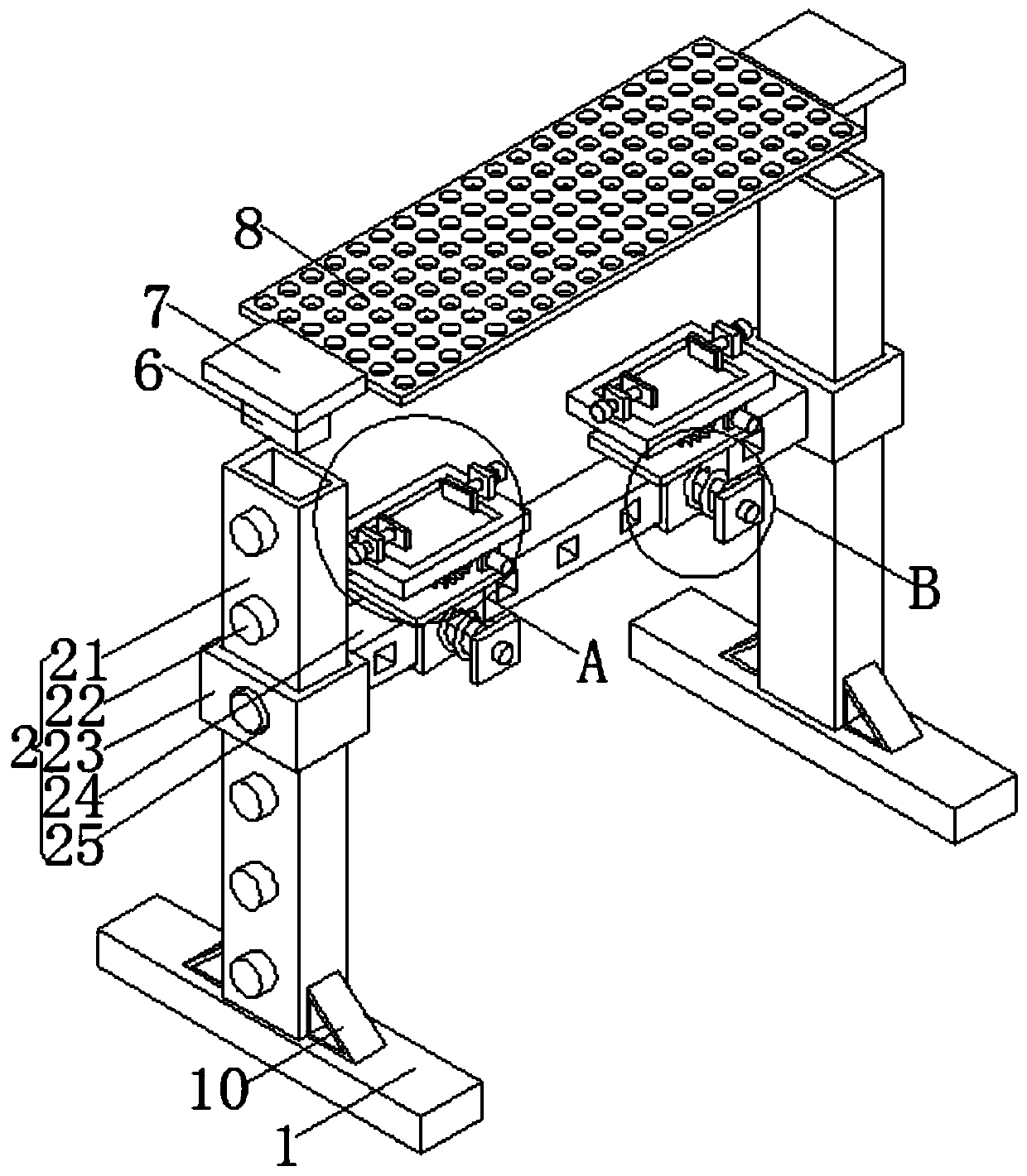
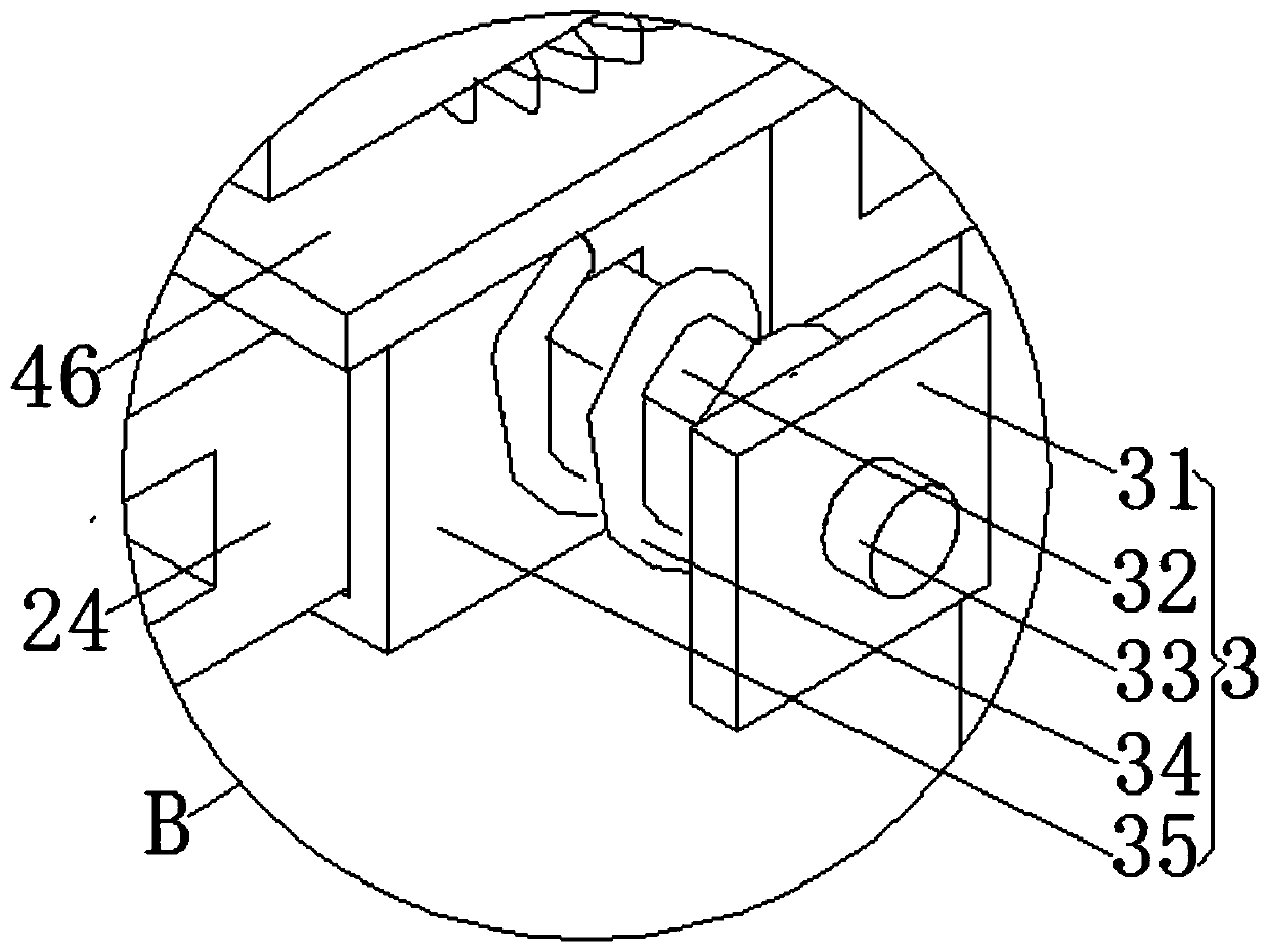
[0023] An audio display stand, including a base 1, a lifting unit 2 and a moving unit 3. There are two bases 1 corresponding to the left and right. The lifting unit 2 includes a support rod 21, an elastic bolt 22, a slider 23, a mounting rod 24 and a positioning hole 25 , there are two support rods 21 and they are respectively arranged in the middle of the tops of the two bases 1, the outer side arrays of the two support rods 21 have elastic latches 22, and the left and right ends of the installation rod 24 are provided with sliders 23, the sliders 23 The sliding hole on the side is slidably connected with the support rod 21. The outer surface of the slider 23 is provided with a positioning hole 25. The positioning hole is matched with the elastic bolt 22. The front side array of the mounting rod 24 has jacks. The height of the sound is adjusted according to the distance of different users, so that the user can feel the difference in sound quality. The outside of the installati...
Embodiment 2
[0025] The difference between this embodiment and Embodiment 1 is:
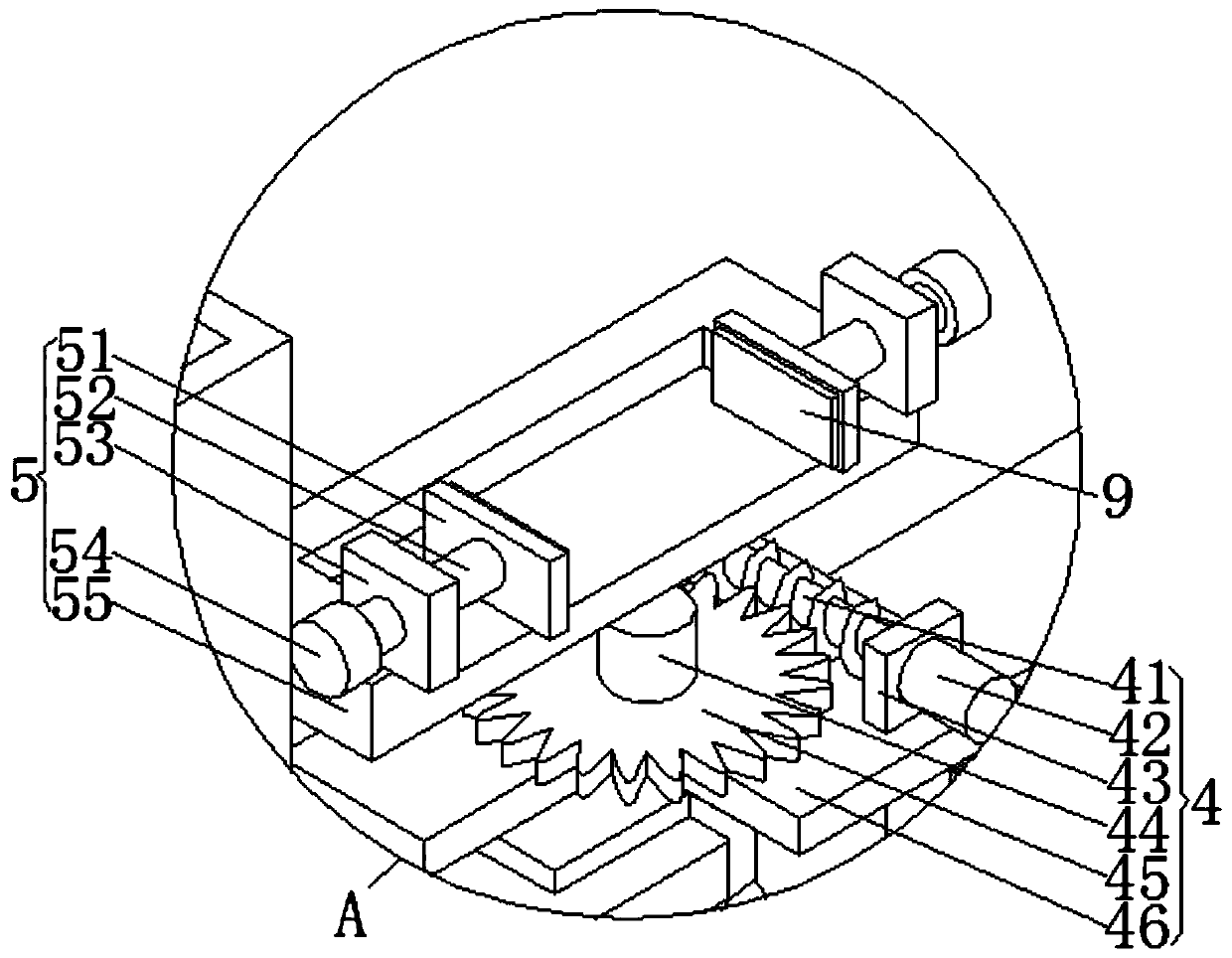
[0026] In this embodiment, the rotating unit 4 includes a worm 41, a runner 42, a mounting plate 43, a connecting shaft 44, a gear 45 and a fixed plate 46, the bottom of the fixed plate 46 is connected with the top of the movable block 35, and the top of the fixed plate 46 is The middle part is rotatably connected with a connecting shaft 44, and the middle part outside the connecting shaft 44 is provided with a gear 45. There are two mounting plates 43 which are correspondingly arranged on the right side of the top of the fixing plate 46. Between the two mounting plates 43, a worm 41 is rotatably connected. , the runner 42 is located at the front end of the mounting plate 43 on the front side, the rear end of the runner 42 is connected with the front end of the worm 41, the worm 41 is meshed with the gear 45, and the top of the connecting shaft 44 is provided with the clamping unit 5.
[0027] The clamping un...
Embodiment 3
[0030] The difference between this embodiment and Embodiment 1 is:
[0031] In this embodiment, it also includes an insert block 6, a protective plate 7 and a dustproof net 8, the left and right ends of the dustproof net 8 are provided with a protective plate 7, and the bottom ends of the two protective plates 7 are provided with an insert block 6, The insert block 6 is plugged into the slot at the top of the support rod 21 .
[0032] It also includes rubber pads 9, there are two rubber pads 9 and they are respectively arranged on the inner surfaces of the two splints 51.
[0033] It also includes a tripod support frame 10, and there are four tripod support frames 10, which are set at the bottom ends of the front and rear sides of the two support rods 21 in groups of two.
[0034] Concretely, set up like this, be provided with insert block 6, protective plate 7 and dust-proof net 8, can effectively prevent dust etc. from being scattered to the top of audio system, and then pr...
PUM
 Abstract
Description
Claims
Application Information
 - R&D
- Intellectual Property
- Life Sciences
- Materials
- Tech Scout
- Unparalleled Data Quality
- Higher Quality Content
- 60% Fewer Hallucinations
Browse by: Latest US Patents, China's latest patents, Technical Efficacy Thesaurus, Application Domain, Technology Topic, Popular Technical Reports.
© 2025 PatSnap. All rights reserved.Legal|Privacy policy|Modern Slavery Act Transparency Statement|Sitemap|About US| Contact US: help@patsnap.com


