Video compression prediction method
A prediction method and video compression technology, applied in digital video signal modification, image communication, electrical components, etc., can solve problems such as poor correlation, reduction of theoretical limit entropy, and impact on the quality of prediction modules, so as to improve accuracy, good deviation correction effect, Optimizing the performance of predictive performance
- Summary
- Abstract
- Description
- Claims
- Application Information
AI Technical Summary
Problems solved by technology
Method used
Image


Examples
Embodiment 1
[0055] See figure 1 , figure 1 It is a flowchart of a video compression prediction method provided by the present invention. The prediction method of the present embodiment includes the following steps:
[0056] S1: Divide the image into multiple MBs of the same size, and select one MB as the current MB;
[0057] S2: Predict the current MB by using a prediction method based on pixel-level multi-component reference, and obtain a first prediction residual of the current MB;
[0058] S3: Predict the current MB by using an adaptive texture gradient prediction method based on inflection point sampling, and obtain a second prediction residual of the current MB;
[0059] S4: Select a final prediction residual of the current MB according to the first prediction residual and the second prediction residual.
[0060]Further, step S2 includes:
[0061] S21: Select the current pixel, and determine multiple pixel components of the current pixel;
[0062] S22: Calculate pixel differenc...
Embodiment 2
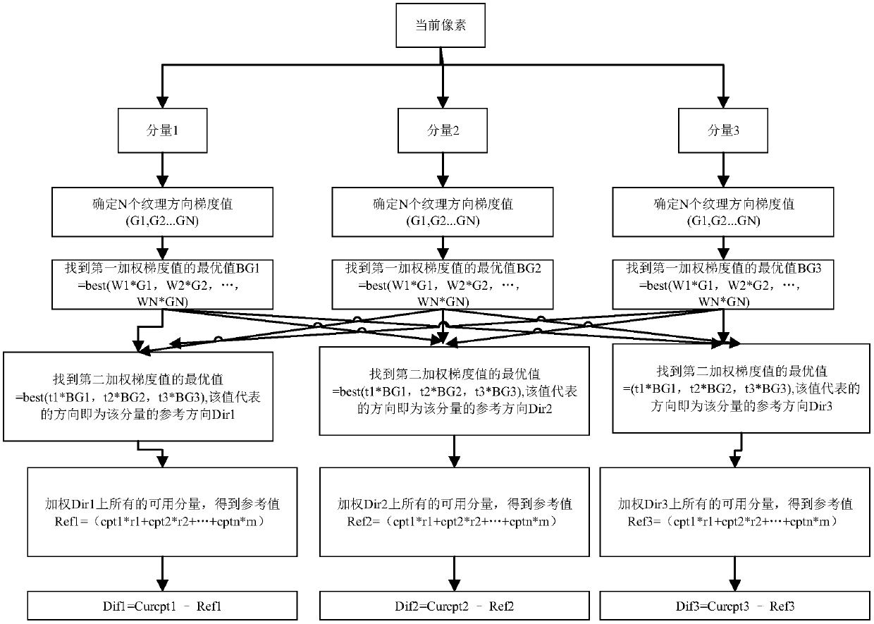
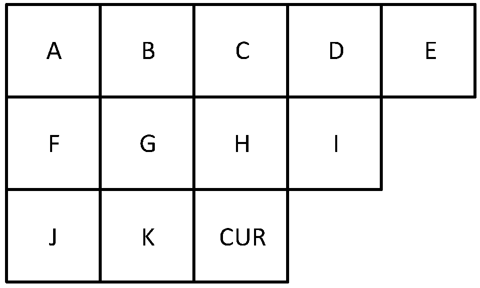
[0098] See Figure 4 with Figure 5 , Figure 4 A schematic diagram of gradient value calculation provided by the embodiment of the present invention; Figure 5 It is a flow chart of another adaptive direction prediction method for pixel-level multi-component reference provided by an embodiment of the present invention. On the basis of the above-mentioned embodiments, this embodiment describes the pixel-level multi-component reference adaptive direction prediction method proposed by the present invention by way of example. In this embodiment, the current pixel is divided into R component, G component and B component, specifically as follows:
[0099] For the three components of the current pixel, determine the three texture direction gradient values G1, G2, and G3 of each component through the surrounding components of each component;
[0100] Preferably, for the R component, the G component, and the B component, according to Figure 4 As shown, ABS(K-H) is a gradient v...
Embodiment 3
[0121] See Image 6 , Image 6 It is a flow chart of a prediction method for adaptive texture gradient based on knee point sampling provided by an embodiment of the present invention. The forecasting method includes the steps of:
[0122] S31: Determine the sampling mode of the current MB;
[0123] S32: Determine the sampling point of the current MB by using a pixel value inflection point sampling method;
[0124] S33: Select multiple prediction modes to predict the sampling points of the current MB, and acquire multiple prediction residuals corresponding to each prediction mode;
[0125] S34: Calculate the residual absolute value sum of each prediction mode, and determine the final prediction mode of the current MB;
[0126] S35: Calculate a second prediction residual of the current MB according to the final prediction manner.
[0127] In this embodiment, step S32 includes:
[0128] S321: Calculate the difference between the pixel value of the current pixel component of...
PUM
 Abstract
Description
Claims
Application Information
 - R&D
- Intellectual Property
- Life Sciences
- Materials
- Tech Scout
- Unparalleled Data Quality
- Higher Quality Content
- 60% Fewer Hallucinations
Browse by: Latest US Patents, China's latest patents, Technical Efficacy Thesaurus, Application Domain, Technology Topic, Popular Technical Reports.
© 2025 PatSnap. All rights reserved.Legal|Privacy policy|Modern Slavery Act Transparency Statement|Sitemap|About US| Contact US: help@patsnap.com