
Quick closing mechanism

A fast, DC motor technology, applied in the direction of protection switch operation/release mechanism, etc., can solve the problems of complex installation, complex structure, low speed of AC motor, etc., and achieve the effect of saving space, reducing height, and reducing manual mechanism settings

Pending Publication Date: 2020-05-05
JIANGSU SUYI ELECTRIC APPLIANCE
View PDF3 Cites 2 Cited by
  • Summary
  • Abstract
  • Description
  • Claims
  • Application Information

AI Technical Summary

Problems solved by technology

[0005] The transmission mechanism on the traditional circuit breaker uses an AC motor to realize the re-clamping-closing operation. The speed of the AC motor is not high, and it cannot achieve fast closing
Moreover, it is impossible to realize the self-clutching of the circuit breaker
Patent document CN110047713A discloses a reclosing transmission mechanism and a molded case circuit breaker. Its structure is relatively complicated and its installation is complicated, and the rack used is a single rack. operate

Method used


Image

  • Quick closing mechanism
  • Quick closing mechanism
  • Quick closing mechanism

Examples


Embodiment approach 1

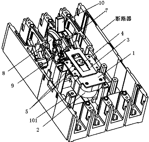
[0037] The invention relates to the field of circuit breakers. It is a mechanism for fast closing on the circuit breaker. It is used based on a molded case circuit breaker and includes a power source for electric closing, a DC motor 2; it is connected with the circuit breaker and used for fixing the DC The motor fixing plate 1 of the motor 2; the inner double-tooth rack 3 that is slidably connected to the upper surface of the motor fixing plate 1 and whose front end is rotatably connected to the lever bracket 8 of the circuit breaker main mechanism; The incomplete gear 4 engaged with the racks on both sides is fixedly connected with the output shaft of the DC motor 2 . In this embodiment, a plurality of through holes 101 are opened around the motor fixing plate 1, and are fixed on the circuit breaker by screws, see the attached figure 1 . Inner double-toothed rack 3 is elongated, hollow in the middle, and the toothed rack of its both sides is arranged relatively, and incomple...

Embodiment approach 2

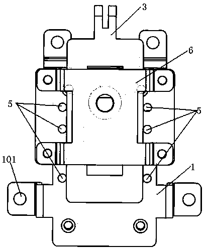
[0041] This embodiment is a further improvement on Embodiment 1. The improvement is as follows: set several stop protrusions 5 on the motor fixing plate 1, the stop protrusions 5 are located on both sides of the inner double-teeth rack 3, and the inner double teeth The rack 3 is limited to a vertical position, and it can only slide forward and backward, but not left and right. A cover plate 6 is arranged above the inner double-toothed rack 3, and the two sides of the cover plate 6 are fixed on the motor fixing plate 1 by screws, so that the inner double-toothed rack 3 is limited up and down and will not fall.

[0042] DC motor 2 output shafts pass cover plate 6 and have a stopper at the end of output shaft, output shaft is just rotatably connected to cover plate 6 like this, and incomplete gear 4 rotates with output shaft rotation.

Embodiment approach 3

[0044]This embodiment is a further improvement on Embodiment 1. The improvement plan is: the motor fixing plate 1 is set in an arched shape, the DC motor 2 is fixed under the arched motor fixing plate 1, and the output shaft of the DC motor 2 passes through the motor fixing plate 1 Connected with the incomplete gear 4, the motor fixing plate is arched so that the DC motor 2 can be placed under the arch, saving space and greatly reducing the height of the product.

[0045] working principle:

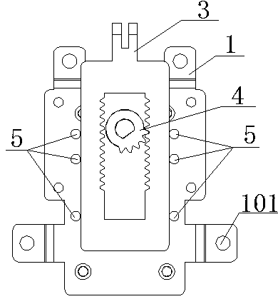
[0046] 1. Such as image 3 As shown, when the circuit breaker is in the opening state, the tooth mouth of the incomplete gear 4 is set upward at this time, and the several tooth mouths set on the incomplete gear 4 do not mesh with the tooth mouths on both sides of the inner double-toothed rack 3, At this time, the switch can be closed manually.

[0047] 2. Such as Figure 4 As shown, when the circuit breaker needs to be buckled again, the DC motor 2 is started, and the incomplete gea...


PUM


Abstract

The invention relates to the technical field of circuit breakers, and discloses a quick switching-on mechanism. The quick switching-on mechanism comprises a direct current motor, a motor fixing platewhich is connected with a circuit breaker and is used for fixing the direct current motor, and an inner double-tooth rack which is slidably connected with the upper surface of the motor fixing plate,and the front end of the inner double-tooth rack is rotatably connected with a circuit breaker main mechanism lever bracket. The quick switching-on mechanism further comprises an incomplete gear whichis positioned in the internal double-tooth rack, can be meshed with the racks on the two sides of the internal double teeth during rotation, and is fixedly connected with an output shaft of the direct current motor. Compared with the prior art, the quick switching-on mechanism has the advantages that self-clutch of the circuit breaker is achieved through the inner double-tooth rack and the incomplete gear; re-buckling-closing operation is reliably achieved; electric operation and manual operation can be achieved at the same time; the rotating speed is increased through the direct current motor; rapid closing of the circuit breaker is achieved; the structure is simple; and installation is convenient.

Description

technical field [0001] The invention relates to the technical field of circuit breakers, in particular to a mechanism for fast closing of molded case circuit breakers. Background technique [0002] The opening and closing actions of traditional molded case circuit breakers need to be completed manually. However, due to the development of smart grids, a variety of assembled molded case circuit breakers appear on the market, and most of the assembled molded case circuit breakers are Cooperate with the handle. [0003] For example, Chinese patent CN207149496U discloses an energy storage electric operating device for a molded case circuit breaker, which installs the transmission mechanism above the molded case circuit breaker to cover the entire handle of the molded case circuit breaker, thereby using the transmission mechanism to drive the handle to operate. Automatic switching, however, this installation method increases the height of the entire molded case circuit breaker, a...

Claims


Application Information

Patent Timeline
IPC IPC(8): H01H71/70
CPCH01H71/70
Inventor 杨雷邓飞李正羊
Owner JIANGSU SUYI ELECTRIC APPLIANCE
Learn More