
Topological optimization method of reflector antenna back frame structure for electrical performance

A topology optimization and electrical performance technology, applied in the field of radar, can solve the problems of considering electrical performance, ignoring the structural relationship of the antenna back frame, unable to be an effective solution for the design of the antenna back frame structure, etc., to achieve the effect of ensuring rationality

Active Publication Date: 2020-05-05
XIDIAN UNIV
View PDF3 Cites 4 Cited by
  • Summary
  • Abstract
  • Description
  • Claims
  • Application Information

AI Technical Summary

Problems solved by technology

Although these literatures can carry out the topological design of the antenna back frame structure from the perspective of a single discipline of structure, they ignore the relationship between the antenna back frame structure and the realization of electrical performance, resulting in a large difference between the topology optimization results and the detailed design results of the antenna back frame structure , cannot be an effective solution to guide the structural design of the antenna back frame
In the literature "Topology optimization of reflector antennas based on integrated thermal-structural-electromagnetic analysis" (Struct Multidisc Optim 2017, 55, 715–722), Hu et al. proposed an antenna electromechanical integrated topology design method under temperature load, but the method did not Electrical performance is considered at the initial stage of topology design, which replaces topology design with detailed design

Method used


Image

  • Topological optimization method of reflector antenna back frame structure for electrical performance
  • Topological optimization method of reflector antenna back frame structure for electrical performance
  • Topological optimization method of reflector antenna back frame structure for electrical performance

Examples


Embodiment Construction

[0056] The present invention will be described in further detail below in conjunction with specific embodiments, but the embodiments of the present invention are not limited thereto.

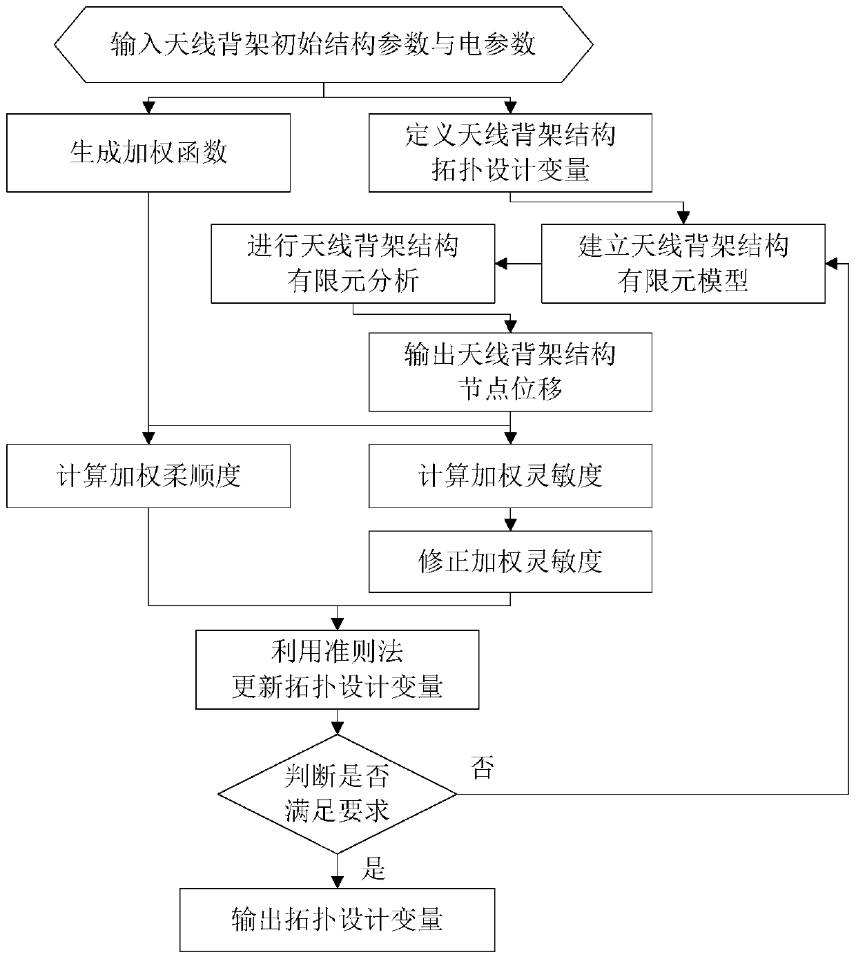
[0057] See figure 1 , figure 1 A flow chart of a topology optimization method for an electrical performance-oriented reflector antenna back frame structure provided by an embodiment of the present invention, including:

[0058] Step 1, input the structural parameters provided by the user including the antenna back frame structure diameter, focal length, longitudinal height, Young's modulus of elasticity, Poisson's ratio, volume ratio, external load, including taper pin parameters, aperture field shape parameters and Electrical parameters including longitudinal attenuation coefficient;

[0059] Step 2, according to the structure diameter, focal length, longitudinal height and volume ratio of the antenna back frame, define the topological design variables of the antenna back frame structure acco...


PUM


Abstract

The invention discloses a topological optimization method of a reflector antenna back frame structure for electrical performance. The topological optimization method comprises the following specific steps: (1) inputting initial structure parameters and electrical parameters of an antenna back frame; (2) defining topological design variables of an antenna back frame structure; (3) generating a weighting function; (4) establishing an antenna back frame structure finite element model; (5) carrying out finite element analysis on the antenna back frame structure; (6) outputting the node displacement of the antenna back frame structure; (7) calculating weighted flexibility; (8) calculating weighted sensitivity; (9) correcting the weighting sensitivity; (10) updating topology design variables byusing a criterion method; (11) judging whether requirements are met or not; and (12) outputting a topological design variable. According to the invention, topological optimization of the reflector antenna back frame structure oriented to electrical performance can be realized, and rigidity distribution of the reflector antenna back frame structure oriented to electrical performance is realized.

Description

technical field [0001] The invention belongs to the technical field of radar, and in particular relates to a topology optimization method for an electrical performance-oriented reflector antenna back frame structure. Background technique [0002] Reflector antennas are widely used in antenna design due to their advantages of high gain and simple structure. In actual engineering, the structural deformation of the reflector antenna due to external loads will affect its electrical performance; in order to ensure the normal operation of the antenna, a certain shape of the back frame structure is usually installed on the back of the reflector. Back frame structure design is the core of reflector antenna structure design. From the level of the structure design of the back frame, topology optimization is the basis of the design of the back frame structure of the reflector antenna. How to design the optimal topology is the key to the topology optimization of the reflector antenna ...

Claims


Application Information

Patent Timeline
IPC IPC(8): G06F30/23
CPCY02T90/00
Inventor 张树新宋君刘子涵邢永涛韩晓童
Owner XIDIAN UNIV
Learn More