
Light guide plate, backlight module and display device

A technology of backlight module and light guide plate, which is applied in the direction of light guide, optics, optical components, etc., can solve the problem of uneven brightness of light guide plate, and achieve the effect of improving uneven brightness and brightness uniformity.

Pending Publication Date: 2020-05-05
RADIANT OPTO ELECTRONICS SUZHOU
View PDF0 Cites 0 Cited by
  • Summary
  • Abstract
  • Description
  • Claims
  • Application Information

AI Technical Summary

Problems solved by technology

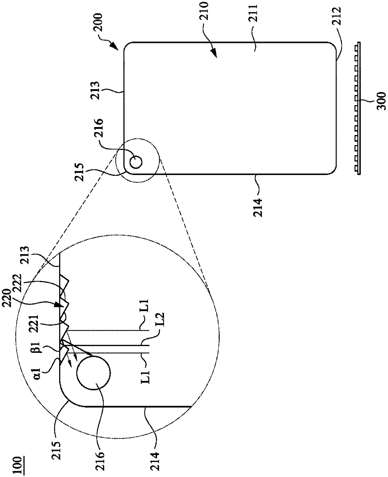
[0004] Therefore, one of the objects of the present invention is to provide a light guide plate, a backlight module and a display device, wherein the microstructure design of the light guide plate can improve the uneven brightness of the light guide plate near the hole, and can improve the overall backlight module. Uniformity of light appearance

Method used


Image

  • Light guide plate, backlight module and display device
  • Light guide plate, backlight module and display device
  • Light guide plate, backlight module and display device

Examples


Embodiment Construction

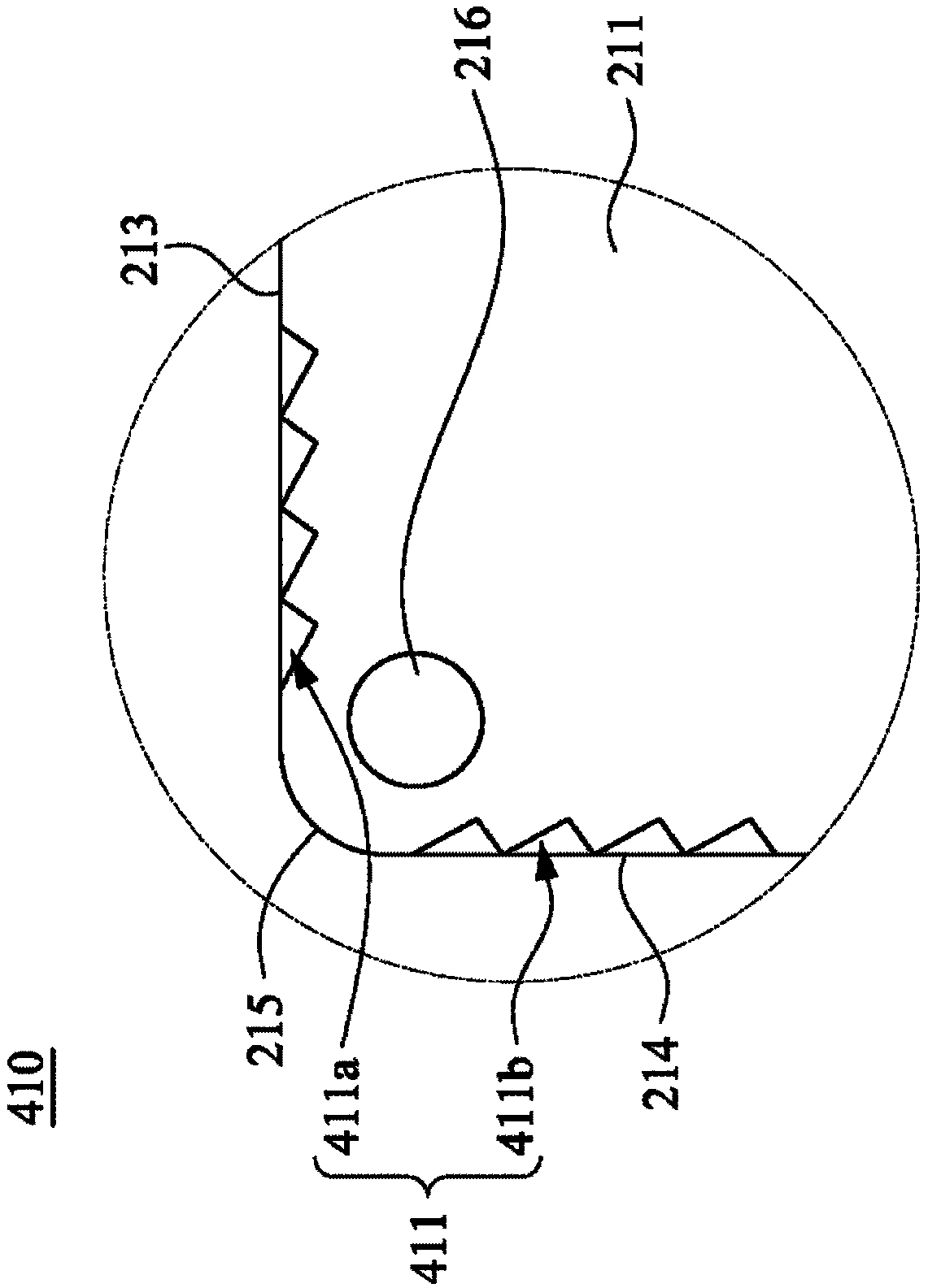
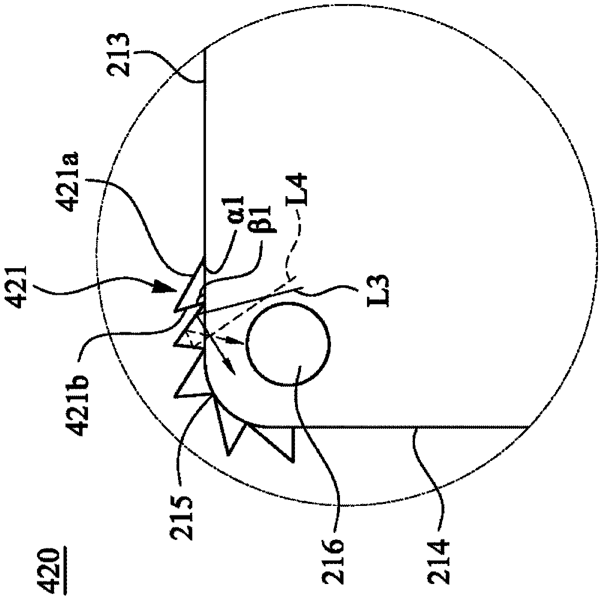
[0026] first refer to figure 1 , which is a schematic diagram showing the device of the backlight module according to the first embodiment of the present invention. The backlight module 100 of this embodiment mainly includes a light guide plate 200 and a light source 300. The light guide plate 200 mainly includes a body 210 and a plurality of microstructures 220 . In this embodiment, the body 210 is a rectangular structure with arc corners around. like figure 1 As shown, the body 210 has an optical surface 211 , a light incident surface 212 , a light incident surface 213 , at least one side surface 214 , and at least one arc surface 215 . In one embodiment, the optical surface 211 may be a light emitting surface or a reflecting surface. like figure 1 As shown, the light incident surface 212 and the light incident surface 213 are respectively connected and erected on opposite sides of the optical surface 211, and the side surface 214 is interposed between the light inciden...


PUM


Abstract

The invention provides a light guide plate, a backlight module and a display device. The light guide plate comprises a body and a plurality of microstructures. The body is provided with an optical surface, a light incident surface, a reverse light incident surface, at least one side surface and at least one arc surface. The incident surface and the reverse incident surface are respectively connected to two opposite sides of the optical surface, the side surface is connected to the optical surface, the incident surface and the reverse incident surface, and the arc surface is located between theside surface and the reverse incident surface. The body is provided with a broken hole penetrating through the optical surface, and the microstructure is arranged on one part, close to the broken hole, of the side surface, the arc surface and / or the reverse incident surface.

Description

technical field [0001] The invention relates to a light guide assembly and its application, in particular to a light guide plate, a backlight module and a display device. Background technique [0002] With the development of display technology, in order to increase the screen-to-screen ratio, some current methods are to dig holes in the light guide plate in the backlight module to accommodate the lens. [0003] However, digging holes in the light guide plate will cause the light traveling in the light guide plate to fail to pass through the hole of the light guide plate, and form a shadow on the opposite side of the hole to receive light, which will seriously affect the appearance of the light guide plate and the uniformity of light output. Contents of the invention [0004] Therefore, one of the objects of the present invention is to provide a light guide plate, a backlight module and a display device, wherein the microstructure design of the light guide plate can improve...

Claims


Application Information

Patent Timeline
IPC IPC(8): G02B6/00
CPCG02B6/0015G02B6/0016
Inventor 张嘉尹黄柏菖林坤政
Owner RADIANT OPTO ELECTRONICS SUZHOU
Learn More