Sound source positioning method and device, medium and equipment
A sound source localization and setting value technology, applied in positioning, measuring devices, neural learning methods, etc., can solve problems such as low accuracy and difficulty in ensuring real-time performance, so as to improve accuracy, reduce algorithm complexity, and ensure real-time performance Effect
- Summary
- Abstract
- Description
- Claims
- Application Information
AI Technical Summary
Problems solved by technology
Method used
Image
Examples
Embodiment 1
[0042] Embodiment 1 of the present invention provides a sound source localization method, the steps of the method can be as follows figure 1 shown, including:
[0043] Step 101, collecting audio time domain signals.
[0044] In this step, the microphone array may be used to collect an audio time-domain signal (such as a speech time-domain signal) of a set duration. In a possible implementation manner, using a microphone array to collect audio time-domain signals may be understood as using a microphone array to collect far-field audio time-domain signals under different signal-to-noise ratios.
[0045] Step 102, perform time domain frequency domain conversion.
[0046] In this step, the collected audio time-domain signal can be converted into an audio frequency-domain signal.
[0047] Considering that when the short-time Fourier transform is used for time-frequency domain conversion, the frequency scale is linear, the conversion complexity is low, the calculation is simple, ...
Embodiment 2
[0063] Embodiment 2 of the present invention provides a sound source localization method, and the steps of the method can be as follows figure 2 shown, including:
[0064] Step 201, collect audio time domain signals.
[0065] In this step, the microphone array may be used to collect far-field audio time-domain signals under different signal-to-noise ratios.
[0066] Step 202. Determine a set of audio time-domain signals for each microphone.
[0067] In this step, a set of audio time-domain signals may be determined for each microphone in the microphone array.
[0068] In this embodiment, assuming that the microphone array includes M microphones, the audio time domain signal collected in step 201 can be collected by each microphone according to the set sampling frequency (such as 16000 sampling points per second). The audio time-domain signals are sampled separately to obtain M channels of audio time-domain signals.
[0069] Step 203, converting into an audio frequency dom...
Embodiment 3
[0094] Embodiment 3 of the present invention provides a sound source localization device, the structure of which can be as follows Figure 4 shown, including:
[0095] The acquisition module 11 is used to utilize the microphone array to collect the audio time-domain signal of setting duration; The conversion module 12 is used to convert the collected audio time-domain signal into an audio frequency-domain signal; The screening module 13 is used to utilize the trained neural network model , determining a frequency point with a signal-to-noise ratio greater than a set value in the audio frequency domain signal; the positioning module 14 is used to perform sound source location using the frequency point with a signal-to-noise ratio greater than a set value;
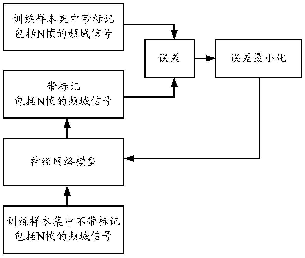
[0096] Wherein, the neural network model utilized in the screening module 13 is obtained in the following manner:
[0097] For each audio frequency domain signal in the training sample set, perform the following operations ...
PUM
 Abstract
Description
Claims
Application Information
 - Generate Ideas
- Intellectual Property
- Life Sciences
- Materials
- Tech Scout
- Unparalleled Data Quality
- Higher Quality Content
- 60% Fewer Hallucinations
Browse by: Latest US Patents, China's latest patents, Technical Efficacy Thesaurus, Application Domain, Technology Topic, Popular Technical Reports.
© 2025 PatSnap. All rights reserved.Legal|Privacy policy|Modern Slavery Act Transparency Statement|Sitemap|About US| Contact US: help@patsnap.com


