
Compact rigid-flexible coupling platform connecting structure and multi-axis motion platform formed by same

A technology of rigid-flexible coupling and connection structure, which is applied in the direction of machine/support, supporting machine, mechanical equipment, etc., can solve the problems of difficult high-precision motion platform construction, easy deformation, weak bearing capacity, etc., to solve the problem of low adjustment stiffness The effect of being cumbersome, lowering the center of gravity, and ensuring fatigue life

Active Publication Date: 2020-05-05
GUANGDONG UNIV OF TECH
View PDF11 Cites 3 Cited by
  • Summary
  • Abstract
  • Description
  • Claims
  • Application Information

AI Technical Summary

Problems solved by technology

However, the two-dimensional micro-motion mechanism based on the flexible hinge of the above two patents also has a weak carrying capacity, and it is difficult to continue to be used in the construction of a large-stroke high-precision motion platform with a higher degree of freedom
Therefore, the patent No. CN201710883865.0 discloses a large load-bearing flexible hinge and a multi-degree-of-freedom combination method. This patent uses a large-load-bearing space flexible mechanism to realize the multi-degree-of-freedom mechanism combined by rigid-flexible coupling platforms. However, the upper layer The entire base of the platform is installed on a flexible platform, with a high center of gravity, large overturning moment, and easy deformation

Method used


Image

  • Compact rigid-flexible coupling platform connecting structure and multi-axis motion platform formed by same
  • Compact rigid-flexible coupling platform connecting structure and multi-axis motion platform formed by same
  • Compact rigid-flexible coupling platform connecting structure and multi-axis motion platform formed by same

Examples


Embodiment

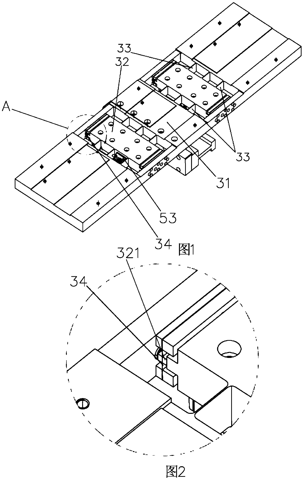
[0030] refer to Figure 1 to Figure 5 , this embodiment relates to a compact rigid-flexible coupling platform connection structure, including an upper platform 1, a lower platform 2, a motion detection element and a driving device, the bottom of the upper platform 1 is movably mounted on the lower platform 2 through a bottom plate 3, so The driving device is installed on the lower platform 2, and the driving device drives the bottom plate 3 and the upper platform 1 to move along the direction of the guide rail; the motion detection element detects the displacement or speed of the upper platform 1.

[0031] This structure directly integrates the bottom plate 3 and the lower platform 2, eliminating the excessive connecting plate in the middle, which reduces the overall center of gravity of the platform, compact structure, flatter Z direction, and can be stacked with multi-layer platform structures to flexibly build The multi-degree-of-freedom high-precision motion platform with ...


PUM


Abstract

The invention discloses a compact rigid-flexible coupling platform connecting structure and a multi-axis motion platform formed by same. The compact rigid-flexible coupling platform connecting structure comprises an upper platform, a lower platform, a motion detection element and a driving device, wherein an upper platform base is designed into a rigid-flexible coupling structure and is mounted ona lower platform guide rail; the driving device is mounted on the lower platform and drives the upper platform to move along the guide rail direction; the motion detection element detects the displacement or speed of an upper platform frame; and a second detection element can be selected to detect the deformation amount or deformation speed of a flexible hinge. According to the compact rigid-flexible coupling platform connecting structure, the bottom of the upper platform and the lower platform are integrated, and a middle connecting plate is omitted, so that the overall gravity center of theplatform is reduced, the structure is compact, and the Z direction is flattened; and moreover, multiple layers of platforms can be superposed, multi-degree-of-freedom motion is realized, and the required multi-degree-of-freedom high-precision motion platform is flexibly constructed. In addition, the rigid-flexible coupling connecting structure adopts the sandwich type flexible hinge, and meanwhile, no assembly error and fatigue life are guaranteed.

Description

technical field [0001] The invention relates to a rigid-flexible coupling platform, in particular to a compact rigid-flexible coupling platform connection structure and a multi-axis motion platform formed thereof. Background technique [0002] Large-stroke high-precision motion platforms are widely used in semiconductor packaging and other fields. In order to comprehensively take into account the requirements of both large stroke and high precision, the macro-micro composite motion platform is widely used in the design of the above-mentioned large stroke high-precision motion platform. In a typical macro-micro compound motion platform, the problem of friction dead zone can be effectively solved based on the flexible hinge, and it has the advantage of greatly improving the positioning accuracy without increasing the cost. Therefore, the micro-motion platform often adopts the flexible hinge-based Design. For example, Patent No. CN201310065603.5 discloses a coaxial macro-micr...

Claims


Application Information

Patent Timeline
IPC IPC(8): F16M11/04F16M11/16F16M11/18
CPCF16M11/045F16M11/048F16M11/18F16M11/16
Inventor 杨志军黄瑞锐苏丽云白有盾
Owner GUANGDONG UNIV OF TECH
Learn More