
Telescopic rotary type hydraulic cylinder

A technology of telescopic rotation and hydraulic cylinders, which is applied in the field of hydraulic cylinders, can solve problems such as high cost and complex hydraulic system structure, and achieve the effect of increasing practicability and reducing cost of use

Inactive Publication Date: 2020-05-05
江都区武坚兴业机械厂
View PDF0 Cites 5 Cited by
  • Summary
  • Abstract
  • Description
  • Claims
  • Application Information

AI Technical Summary

Problems solved by technology

[0004] The purpose of the present invention is to solve the problem that the telescopic rotary hydraulic cylinder in the prior art has the disadvantages of complex structure and high cost of the overall hydraulic system by adding other hydraulic systems, and proposes a telescopic rotary hydraulic cylinder

Method used


Image

  • Telescopic rotary type hydraulic cylinder
  • Telescopic rotary type hydraulic cylinder

Examples


Embodiment Construction

[0019] The following will clearly and completely describe the technical solutions in the embodiments of the present invention with reference to the accompanying drawings in the embodiments of the present invention. Obviously, the described embodiments are only some, not all, embodiments of the present invention.

[0020] In describing the present invention, it should be understood that the terms "upper", "lower", "front", "rear", "left", "right", "top", "bottom", "inner", " The orientation or positional relationship indicated by "outside", etc. is based on the orientation or positional relationship shown in the drawings, and is only for the convenience of describing the present invention and simplifying the description, rather than indicating or implying that the referred device or element must have a specific orientation, so as to Specific orientation configurations and operations, therefore, are not to be construed as limitations on the invention.

[0021] refer to Figure ...


PUM


Abstract

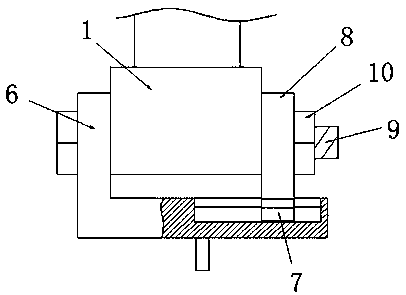
The invention discloses a telescopic rotary type hydraulic cylinder. The telescopic rotary type hydraulic cylinder comprises a base, wherein a hydraulic cylinder is fixedly arranged at the upper end of the base, the upper end of the base is fixedly provided with a protective shell located outside the hydraulic cylinder, a moving block is fixedly arranged at the tail end of a piston rod of the hydraulic cylinder, the upper end of the moving block is vertically and rotationally connected with a screw rod, a first threaded hole is formed in the upper end of the protective shell, the rod wall of the screw rod is in threaded connection with the protective shell through the first threaded hole and the upper end of the screw rod extends to the outside of the protective shell, a L-shaped supporting plate is arranged below the base, a T-shaped sliding groove is transversely formed in the upper end of the horizontal part of the L-shaped supporting plate, the inner part of the T-shaped sliding groove is slidably connected with a T-shaped sliding block, the upper end of the T-shaped sliding block is fixedly connected with a clamping plate, the base is located between the L-shaped supporting plate and the clamping plate, and the base is in fastening connection with the L-shaped supporting plate and the clamping plate through bolts and nuts. According to the telescopic rotary type hydrauliccylinder, the structure is simple, the use cost is reduced, and the practicability of the hydraulic cylinder is improved.

Description

technical field [0001] The invention relates to the technical field of hydraulic cylinders, in particular to a telescopic rotary hydraulic cylinder. Background technique [0002] The hydraulic cylinder is a hydraulic actuator that converts hydraulic energy into mechanical energy. When it is used to realize reciprocating motion, the deceleration device can be eliminated, and there is no transmission gap, and the movement is stable. It is widely used in various mechanical hydraulic systems. The traditional hydraulic cylinder includes a cylinder body, a piston and a piston rod. There are oil inlet and outlet ports on the cylinder body. The movement of the piston and piston rod is realized through the entry and exit of hydraulic oil, and various control functions are realized through external components. The hydraulic rod The motions are linear motions, and the driven external components also do linear motions. [0003] In the actual production process, many external components...

Claims


Application Information

Patent Timeline
Patent Type & Authority Applications(China)
IPC IPC(8): F15B15/14
CPCF15B15/14
Inventor 不公告发明人
Owner 江都区武坚兴业机械厂
Learn More