


Quick Research
Generate reliable direction feasibility study reports for your R&D in just a few steps.

Technical Q&A
Discover and master advanced knowledge NOW. Basics, ideas, possibilities, all at once.

Find Solutions
As an expert in R&D theories, this can generate solutions to your technical problems instantly.

Evaluate Feasibility
Analyze your overall solution with one click, know your potential R&D risks in advance.

Monitor Landscape
Get weekly tech updates, stay abreast of the latest tech innovations and key insights.
Drill rod deviation rectifying clamping device for geotechnical engineering
A clamping device and geotechnical engineering technology, which is applied in the direction of drill pipes, earthwork drilling, supporting devices, etc., can solve the problems of inconvenient installation of drill pipes, space occupation, and large upper space
- Summary
- Abstract
- Description
- Claims
- Application Information
AI Technical Summary
Problems solved by technology
Method used
Image

Examples
Embodiment 1
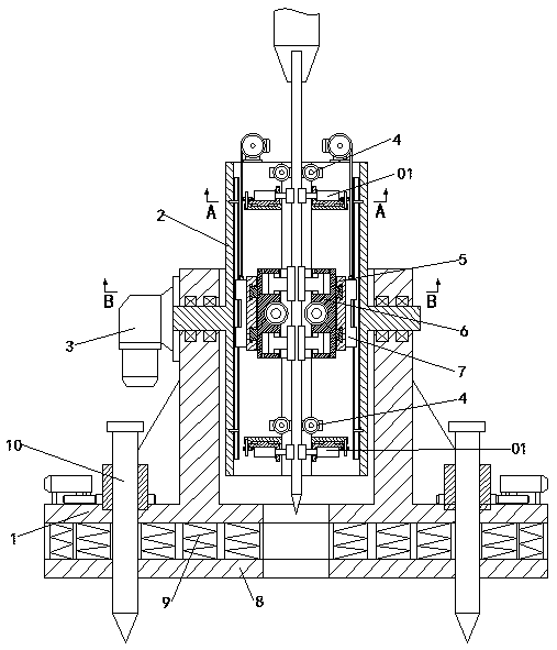
[0037] A kind of geotechnical engineering drill pipe deflection correcting and clamping device of this embodiment, such as figure 1 , Figure 6 , Figure 7 As shown, it includes a base 1, on which a deviation correction base 2 is installed to rotate along the horizontal axis, and a rotating device 3 that drives the deviation correction base 2 to rotate is also arranged on the base 1; the deviation correction base 2 There is a channel for the drill pipe to pass through in the axial direction, and the two ends of the channel are respectively provided with a deviation-correcting clamping device 01, and one side of the deviation-correcting clamping device 01 is coaxially provided with a drill-pipe guiding device 4; the deviation-correcting base On the base 2, a locking frame 5 is slid in the axial direction between the deviation-correcting clamping devices 01 at both ends. The locking frame 5 is provided with a through hole for the drill pipe to pass through. The inside of the th...
Embodiment 2
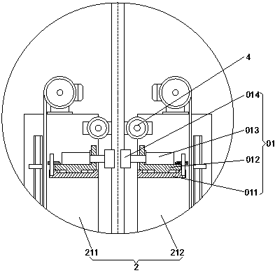
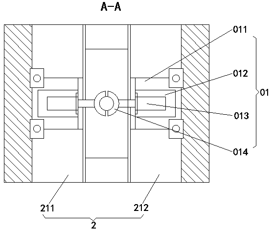
[0045] This embodiment is further optimized on the basis of embodiment 1, such as figure 2 , image 3 , Figure 6 , Figure 7 As shown, the deviation correction clamping device 01 includes a deviation correction installation seat 011, a deviation correction fastening seat 012, a deviation correction oil cylinder 013, and a deviation correction chuck 014. On the side, the deviation correction mounting seat 011 is slidably installed with a deviation correction fastening seat 012 along the direction perpendicular to the axial direction of the deviation correction base 2, and the deviation correction fastening seat 012 is installed with a deviation correction The oil cylinder 013, the end of the push rod of the deviation correction oil cylinder 013 is equipped with a deviation correction chuck 014 for clamping the drill pipe.
[0046] The deviation correction support 2 includes a left deviation correction support 211 and a right deviation correction support 212 symmetrically a...
Embodiment 3
[0053] This embodiment is further optimized on the basis of above-mentioned embodiment 1 or 2, such as Figure 4 and Figure 5 As shown, the drill pipe clamping device 6 includes a clamping ring seat 61, a drill pipe chuck 62, and a clamping piston 63. The clamping ring seat 61 is rotatably arranged in the through hole of the locking frame 5. On the inner ring surface of the clamping ring seat 61, there are at least two piston cavities perpendicular to the axial direction of the drill rod symmetrically about the center of the circle. A clamping piston 63 is slidably arranged in the piston cavity, and the clamping piston 63 separates the piston cavity. It is the first cavity 111 and the second cavity 222, and the first cavity 111 and the second cavity 222 communicate with the outside through hydraulic pipes respectively; one end of the clamping piston 63 extends out of the piston cavity and connects with the One side of the drill chuck 62 is attached.
[0054] The first chamb...
PUM
 Abstract
Description
Claims
Application Information
 - R&D Engineer
- R&D Manager
- IP Professional
- Industry Leading Data Capabilities
- Powerful AI technology
- Patent DNA Extraction
Browse by: Latest US Patents, China's latest patents, Technical Efficacy Thesaurus, Application Domain, Technology Topic, Popular Technical Reports.
© 2024 PatSnap. All rights reserved.Legal|Privacy policy|Modern Slavery Act Transparency Statement|Sitemap|About US| Contact US: help@patsnap.com