
Reconstruction and extension engineering connector structure based on C-shaped grip beam and construction method thereof

A technology of interface structure and engineering, applied in the direction of building structure, construction, etc., can solve problems such as inability to effectively bear shear force and bending moment, and weak connection, so as to improve the integrity of force and deformation coordination, improve the overall rigidity, The effect of high economic and social benefits

Pending Publication Date: 2020-05-05
CHINA RAILWAY FIRST SURVEY & DESIGN INST GRP
View PDF0 Cites 0 Cited by
  • Summary
  • Abstract
  • Description
  • Claims
  • Application Information

AI Technical Summary

Problems solved by technology

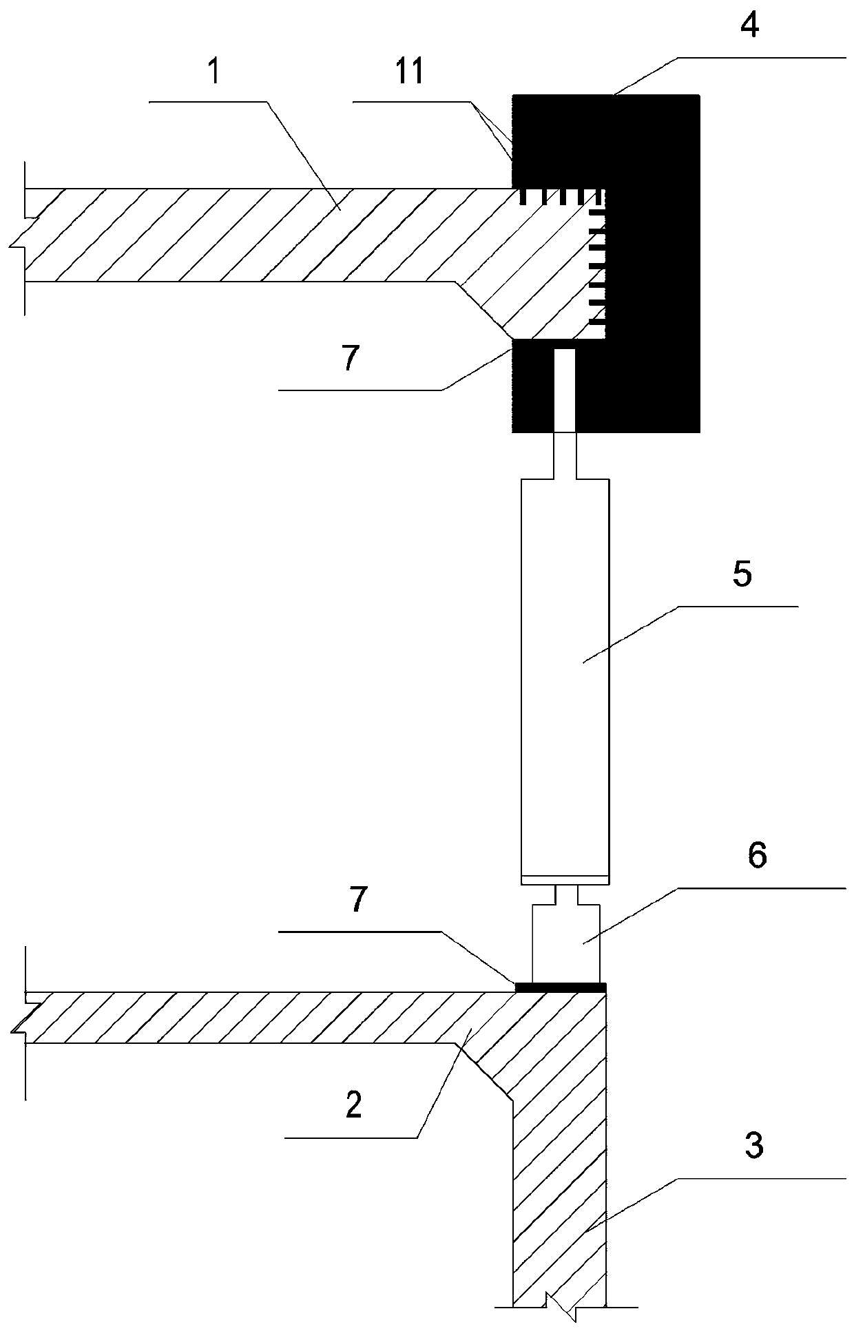
[0004] The purpose of the present invention is to provide an interface structure and construction method for reconstruction and expansion projects based on C-shaped occlusal beams. C-shaped beams are applied between the existing structure and the newly-built structure, and the existing structure is triangulated through the C-shaped beams. Effective clamping, transforming the tensile stress corresponding to the conventional structural butt joint method into the combined bending-shear-torsional stress after C-beam clamping, effectively improving the weak connection between the old and new structures, which cannot effectively bear the shear force and bending moment Improve the integrity and mechanical performance of the joint parts of the new and old structures, improve the structural stability and durability of the reconstruction and expansion projects, and meet the needs of various complex underground engineering constructions

Method used


Image

  • Reconstruction and extension engineering connector structure based on C-shaped grip beam and construction method thereof
  • Reconstruction and extension engineering connector structure based on C-shaped grip beam and construction method thereof
  • Reconstruction and extension engineering connector structure based on C-shaped grip beam and construction method thereof

Examples


Embodiment Construction

[0038] The present invention will be described in detail below in combination with specific embodiments.

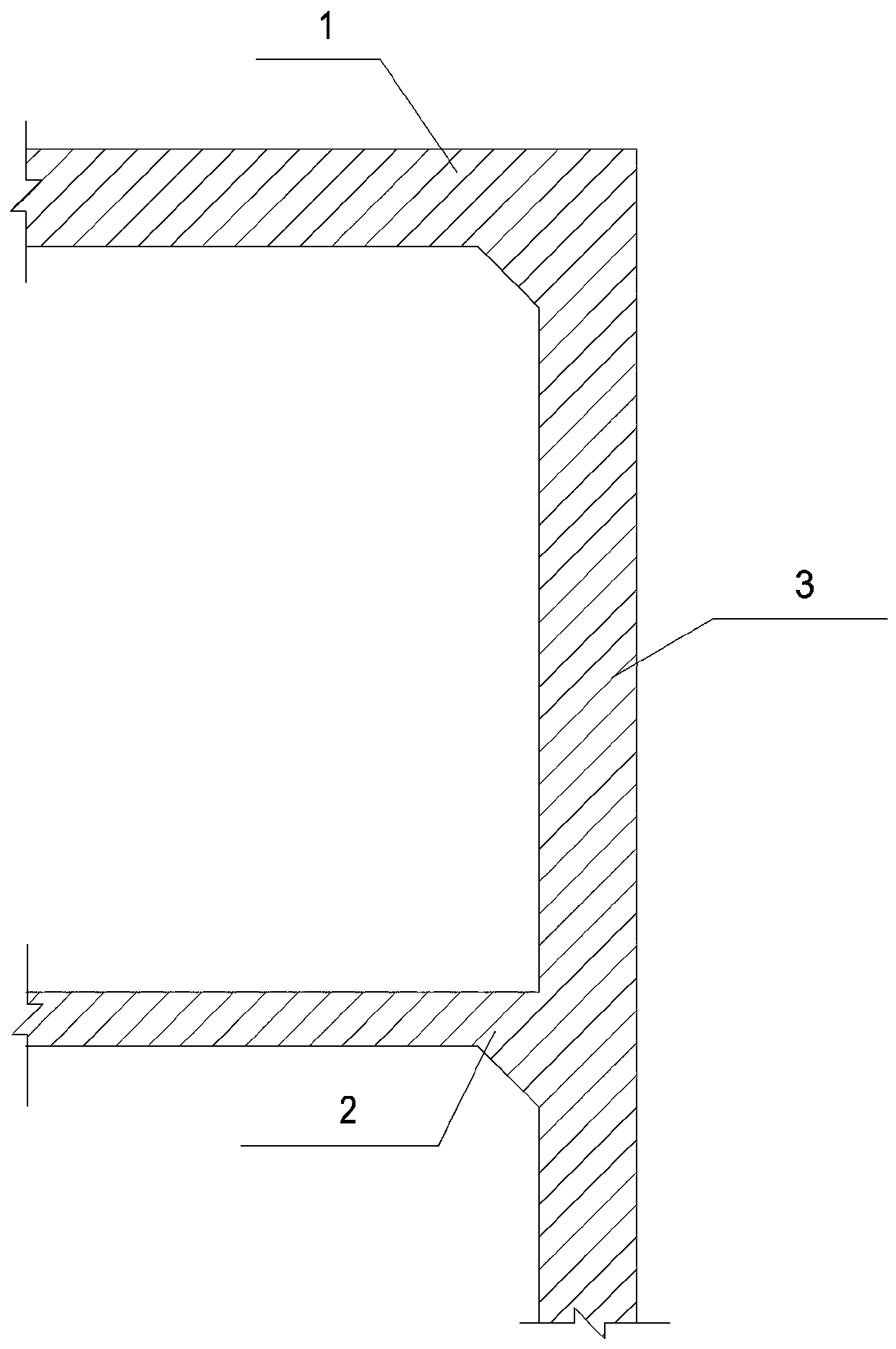
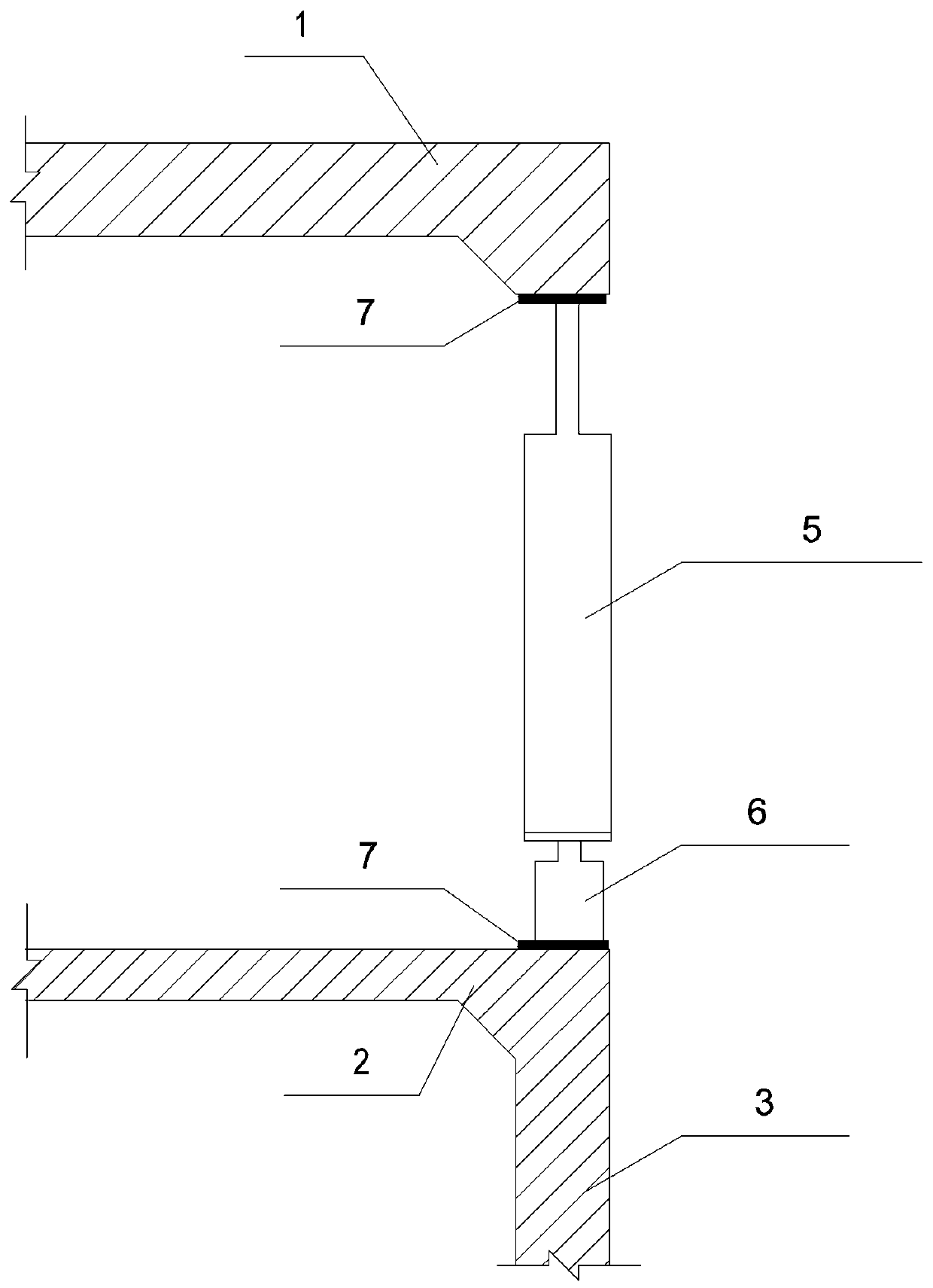
[0039] The present invention relates to the interface structure of reconstruction and extension project based on C-shaped occlusal beam, the interface structure includes the new structure and its accessories at the junction of the old and new structures, the interface structure is rigidly connected with the existing structure and the new structure, and the existing part includes the existing Structural roof 1 and existing structural middle plate 2 or bottom plate, the newly-built part includes newly-built structural roof 8 and newly-built structural middle plate 9 or bottom plate; C-shaped beam 4 and C-shaped The notch of the beam 4 faces the existing structure, forming a three-side clamp on the roof 1 of the existing structure, and the other side is rigidly connected to the roof 8 of the new structure; the middle plate 2 or bottom plate of the existing structure is rigidl...


PUM


Abstract

The invention relates to a reconstruction and extension engineering connector structure based on a C-shaped grip beam and a construction method thereof. The connector structure comprises a newly-madestructure and accessories of the newly-made structure, wherein the newly-made structure and the accessories of the newly-made structure are arranged in a connection position of an existing structure and a newly-constructed structure; the connector structure is in rigid connection with the existing structure and the newly-constructed structure; an existing part comprises an existing structure top plate, side walls and an existing structure middle plate or bottom plate; a newly-constructed part comprises a newly-constructed structure top plate, side walls and a newly-constructed structure middleplate or bottom plate; a C-shaped beam is arranged between the existing structural top plate and the newly-constructed structure top plate; a notch faces the existing part; the upper and lower sidesclamp the existing structure top plate; the other side is in rigid connection with the newly-constructed structure top plate; and the existing structure middle plate or bottom plate is in rigid connection with the newly-constructed structure middle plate or bottom plate. The C-shaped beam clamped and connected with the existing structure top plate converts a connector structure using tensile stress as a main part in a conventional flat connection mode into a superposed component bearing combined bending-shear-torsion action; the stress integrity and deformation coordination are improved; and the integral rigidity of the connector part of new and old structures is improved.

Description

technical field [0001] The invention belongs to the technical field of underground engineering, and in particular relates to a C-shaped occlusal beam-based reconstruction and extension engineering interface structure and a construction method thereof. Background technique [0002] With the rapid development of the economy, in order to guide the rational layout and orderly development of the city, make full use of underground resources to provide a broad extension space for urban development, in recent years, the underground space has gradually developed in a diversified and hierarchical direction, and various existing structures have been improved. With the increasing number of expansion projects, the requirements for the protection of existing structures, the effective connection and coordinated deformation of new and old structures are becoming more and more stringent. [0003] Reconstruction and expansion projects often have unreasonable structural types and concentrated ...

Claims


Application Information

Patent Timeline
Patent Type & Authority Applications(China)
IPC IPC(8): E04B1/58E04B1/20
CPCE04B1/5818E04B1/20Y02E10/20
Inventor 戴志仁廖晖张庆闯喻忠吕海军赵亚军段建锋许红春刘彤张毓斌李谈查家宏王维马琳琳王文彬王耀辉陈新平孟宪全
Owner CHINA RAILWAY FIRST SURVEY & DESIGN INST GRP
Learn More