A post-processing method for induction wheel processing

A technology of induction wheel and treatment box, which is applied in the direction of liquid cleaning method, dry goods treatment, chemical instruments and methods, etc., can solve the problems of increased production cost, large energy loss, heavy workload, etc., and achieve automatic operation, Guaranteed accuracy, practical operation and reasonable effect

Active Publication Date: 2021-02-26
ZHEJIANG UNIV OF WATER RESOURCES & ELECTRIC POWER
View PDF7 Cites 0 Cited by
  • Summary
  • Abstract
  • Description
  • Claims
  • Application Information

AI Technical Summary

Problems solved by technology

In the existing post-processing, for the two processes of cleaning and drying, generally two kinds of equipment are used to treat the inducer separately, which has a large workload and a large loss of energy consumption.
And the price of the two devices is also high, increasing the production cost

Method used


Image

  • A post-processing method for induction wheel processing
  • A post-processing method for induction wheel processing
  • A post-processing method for induction wheel processing

Examples


Embodiment Construction

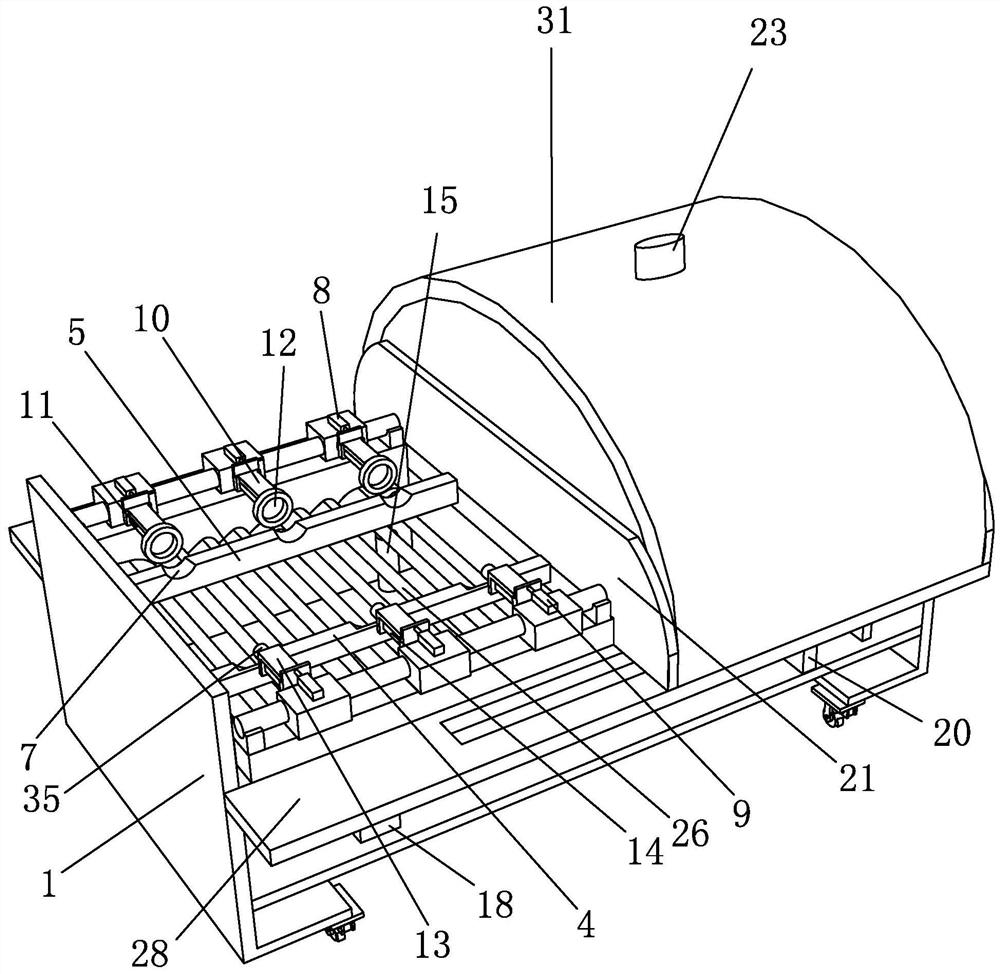
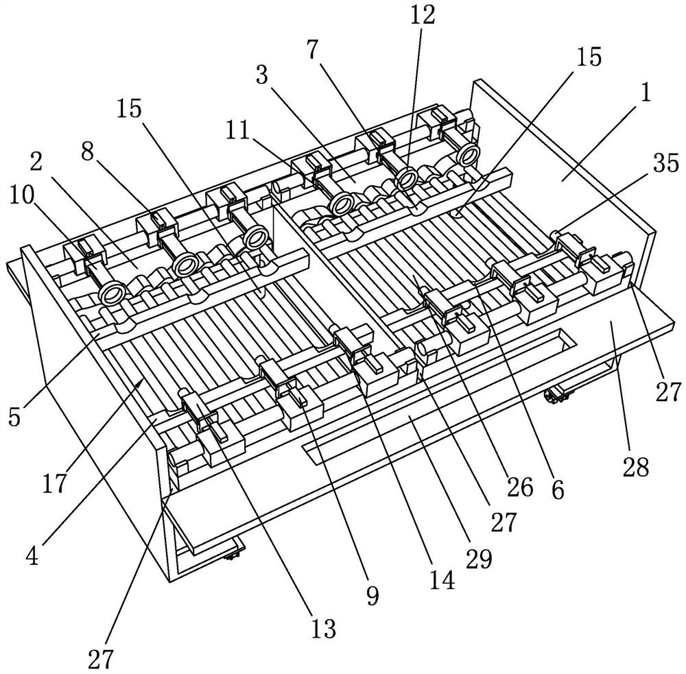
[0032] Such as Figure 1 to Figure 7 Shown, be a kind of post-processing method for induction wheel processing of the present invention, comprise the steps:

[0033] a, the placement of the inducer 32:

[0034] 1) First place the induction wheel 32 on the placement platform 16 of the left cavity 2 of the processing box 1, and the end of the induction wheel 32 connected to the shaft is snapped into the front groove 6 on the front limit plate 4 of the placement platform 16, and induces The other end of the wheel 32 is clamped in the corresponding rear groove 7 on the rear limiting plate 5 of the placement table 16 until the clamping placement of all the induction wheels 32 in the left cavity 2 is completed; through the front groove 6 and the rear groove 7. Realize the preliminary clamping and positioning of the induction wheel 32 to ensure the accuracy of the actual material position, thereby facilitating the precise positioning between the subsequent ferrule 12, the insertion ...


PUM


Abstract

The invention discloses a post-processing method for processing an inducer, comprising the following construction steps: a. placing the inducer; b. scouring and cleaning the inducer; c. drying the inducer. In the present invention, the cleaning and drying processes are directly performed in one processing box, which saves equipment costs and reduces the price of finished products, and the processing box is divided into two cavities, the left cavity and the right cavity, and cleaning is realized through the two cavities. The movement of the protective cover realizes the cyclic exchange of functions between the two cavities. The cavity above which the protective cover is located is the drying processing area, and the other cavity is the feeding area. In the cleaning area, the two chambers operate synchronously, so as to realize the continuous post-processing operation of the inducer, effectively improving the processing rate, and the equipment in the two chambers is exactly the same, so that the right chamber can be loaded, cleaned and dried. The process is the same as the operation process of the left cavity, which is more convenient for actual operation control and reduces the difficulty of operation.

Description

technical field [0001] The invention relates to a post-processing method for induction wheel processing. Background technique [0002] The inducer is to reduce the static positive suction pressure of the centrifugal pump, which is achieved by increasing the static pressure at the inlet of the first stage impeller of the centrifugal pump by the inducer. The swirling flow through the inducer to the outflow also plays a role in reducing the net positive suction head of the centrifugal pump. In order to avoid that when the inducer is working in the overload area, the steam bubbles on the pressure surface of the vane will block the flow channel cross-section - cavitation phenomenon, we often make the design flow of the inducer and the rated flow of the centrifugal pump 1.5-- 2.3 times, so when the centrifugal pump is working, the inducer is always running in the partial load working area, and gives the centrifugal pump impeller the necessary boost. [0003] In the milling proce...

Claims


Application Information

Patent Timeline
Patent Type & Authority Patents(China)
IPC IPC(8): B08B3/02B08B13/00F26B3/04F26B21/00F26B25/00
CPCB08B3/022B08B13/00F26B3/04F26B21/004F26B25/003
Inventor 郭晓梅包志炎施高萍刘学应
Owner ZHEJIANG UNIV OF WATER RESOURCES & ELECTRIC POWER
Why Eureka
Try Eureka