Eureka AIR delivers breakthrough ideas for toughest innovation challenges, trusted by R&D personnel around the world.

A vertical cold inlay device and inlay method for small ceramic matrix composite materials

A composite material and ceramic-based technology, which is applied in the field of vertical cold mounting devices for small ceramic-based composite materials, can solve the problem of inapplicable small ceramic-based composite materials for vertical mounting and fixing, the inability to freely change the relative position of the sample, and the non-adjustable position of the thin-section sample, etc. problems, to achieve the effect of small operation difficulty, avoid breakage, and avoid waste

Active Publication Date: 2020-12-29
NANJING UNIV OF AERONAUTICS & ASTRONAUTICS
View PDF13 Cites 2 Cited by
  • Summary
  • Abstract
  • Description
  • Claims
  • Application Information

AI Technical Summary

Problems solved by technology

With this design, the fixation of the sample will be strictly limited by the position of the sample hole, and the relative position of the sample in the mounting mold cannot be freely changed
The utility model patent 201420502419.2 discloses a "thin slice metallographic inlay sample fixture", which can only be used to inlay thin slice structure samples and the position of thin slice samples cannot be adjusted
Invention patent CN105067416A discloses a "metallographic cold mounting device with adjustable sample mounting position and angle", which can adjust the mounting position and angle of small samples with irregular shapes. The clamping device is inlaid together with the sample, and the material will be damaged when the sample is pulled out after the resin solidifies, thus affecting the subsequent microstructure observation, so this device is not suitable for vertical inlaying and fixing of small ceramic matrix composite materials

Method used


Image

  • A vertical cold inlay device and inlay method for small ceramic matrix composite materials
  • A vertical cold inlay device and inlay method for small ceramic matrix composite materials
  • A vertical cold inlay device and inlay method for small ceramic matrix composite materials

Examples


Embodiment Construction

[0039] Embodiments of the present invention will be further described in detail below in conjunction with the accompanying drawings.

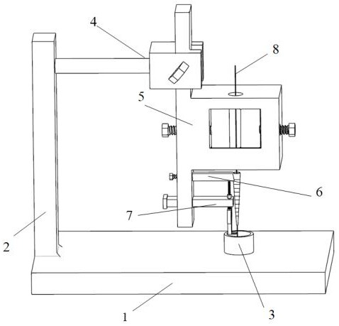
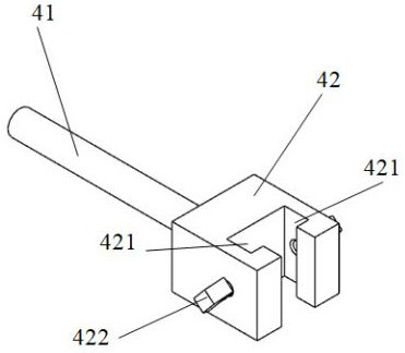
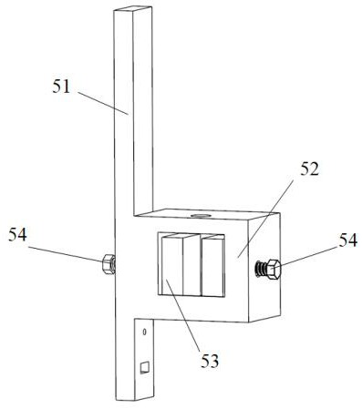
[0040] like figure 1 As shown, a vertical cold mounting device for small ceramic-based composite materials, which includes a base 1, a vertical column 2, a mosaic mold 3, a horizontal fixing device 4, a vertical moving device 5, a vertical fixing device 6 and a cutting device 7; , the vertical column 2 is vertically arranged, the lower end of the vertical column 2 is fixed on the base 1, the inlay mold 3 is detachably fixed on the upper surface of the base 1, the inlay mold 3 is a barrel-shaped structure with a closed lower end, and the horizontal fixing device 4 Including beam 41 and chuck 42, one end of beam 41 is fixedly connected to the upper part of the vertical column 2, and the other end is fixedly connected to chuck 42, and the fastening knob 422 is installed on the chuck 42 to adjust the tightness of the chuck 42, the vertical movement...


PUM


Abstract

The invention discloses a ceramic-based small composite material vertical cold embedding device and an embedding method. The device comprises a base, a vertical upright, an embedding die, a horizontalfixing device, a vertical moving device, a vertical fixing device and a cutting device; the embedding die is of a barrel-shaped structure with a closed lower end; the horizontal fixing device comprises a beam and a chuck; the vertical moving device comprises a clamping plate, a fixed frame, two sliding blocks and a threaded screw; the fixed frame is a mouth-shaped frame with an observation clamping slot in the middle, and is provided with a transverse threaded hole; vertical through holes are symmetrically arranged at an upper side frame center and a lower side frame center of the fixed frame; a testing sample manufactured by the ceramic-based small composite material can vertically penetrate through the two vertical through holes and the observation clamping slot; the cutting device comprises a movable push-pull rod, a vertical screw and a vertical scissor. The testing sample can be kept to be vertical when the testing sample is firmly fixed, and the vertical fixing problem of the ceramic-based small composite material during cold embedding is solved.

Description

technical field [0001] The invention belongs to the technical field of material performance detection, and in particular relates to a vertical cold inlay device and inlay method for small ceramic matrix composite materials. Background technique [0002] Continuous fiber reinforced ceramic matrix composites have shown superiority in the aerospace field because of their high specific strength, high specific modulus, low density, and good high temperature resistance. As a kind of unidirectional continuous fiber reinforced ceramic matrix composites, due to its simple structure and small size, it is often used to study the microstructure of unidirectional continuous fiber reinforced ceramic matrix composites. [0003] When observing the crystal structure, microscopic morphology and element distribution of the cross-section of the ceramic matrix small composite material, the cross-section of the material needs to be polished and smoothed. However, due to its small radial size, it...

Claims


Application Information

Patent Timeline
Patent Type & Authority Patents(China)
IPC IPC(8): G01N1/32
CPCG01N1/32
Inventor 孙志刚陈西辉丁俊杰宋迎东牛序铭陈壮壮
Owner NANJING UNIV OF AERONAUTICS & ASTRONAUTICS
Why Eureka
Eureka Blog
Learn More