Testing device and method capable of achieving up-and-down climbing in counter-force well and turnover plate standing

A technology of test device and flap, which is applied in the direction of ladders, buildings, building structures, etc., can solve the problems of inconvenient handling of straight ladders or ladders, lack of guarantee of personnel safety, poor test efficiency, etc., and achieve saving Effects of working time, saving space, and ensuring safety

Pending Publication Date: 2020-05-01
ZHEJIANG UNIV CITY COLLEGE
View PDF0 Cites 0 Cited by
  • Summary
  • Abstract
  • Description
  • Claims
  • Application Information

AI Technical Summary

Problems solved by technology

However, because the depth of the reaction well is too large, it is very difficult for the test personnel to install and repair the experimental instruments on the outer wall of the segment, and to repair the loading system.
If it is difficult to ensure the safety of the staff only by relying on straight ladders or step ladders, and there is little space left between each set of jacks, it is inconvenient to carry straight ladders or step ladders, which will affect the test efficiency
[0004] In summary, although the reaction well test makes up for the shortcomings of the traditional segment test in terms of loading mode, simulated working conditions and accuracy of test results in terms of test design, there are still some problems in this test platform, that is, there is no equipment to assist The test personnel carry out the test operation and equipment maintenance on the outer wall of the segment, so that the safety of the personnel cannot be guaranteed, and the test efficiency is not good, etc.

Method used


Image

  • Testing device and method capable of achieving up-and-down climbing in counter-force well and turnover plate standing
  • Testing device and method capable of achieving up-and-down climbing in counter-force well and turnover plate standing
  • Testing device and method capable of achieving up-and-down climbing in counter-force well and turnover plate standing

Examples


Embodiment Construction

[0031] The present invention will be further described below in conjunction with the embodiments. The following examples are illustrative only to aid in the understanding of the present invention. It should be pointed out that for those skilled in the art, without departing from the principle of the present invention, several improvements and modifications can also be made to the present invention, and these improvements and modifications also fall within the protection scope of the claims of the present invention.

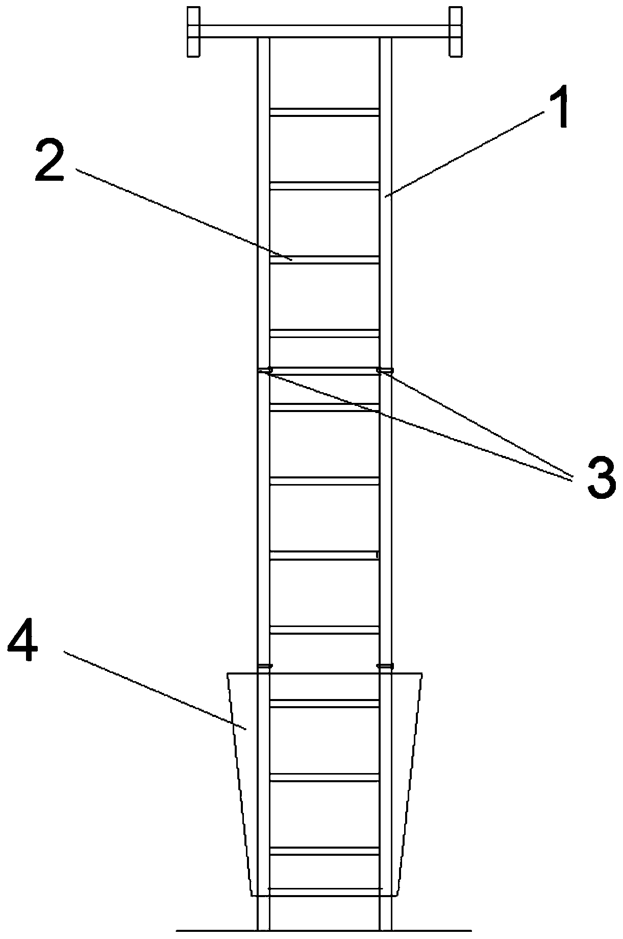
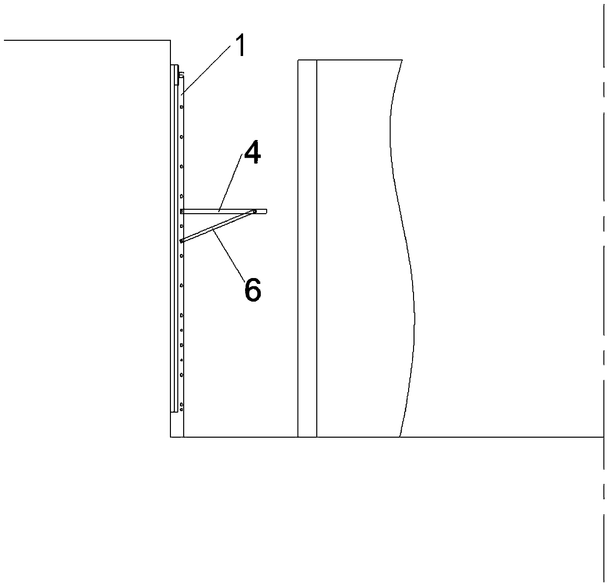
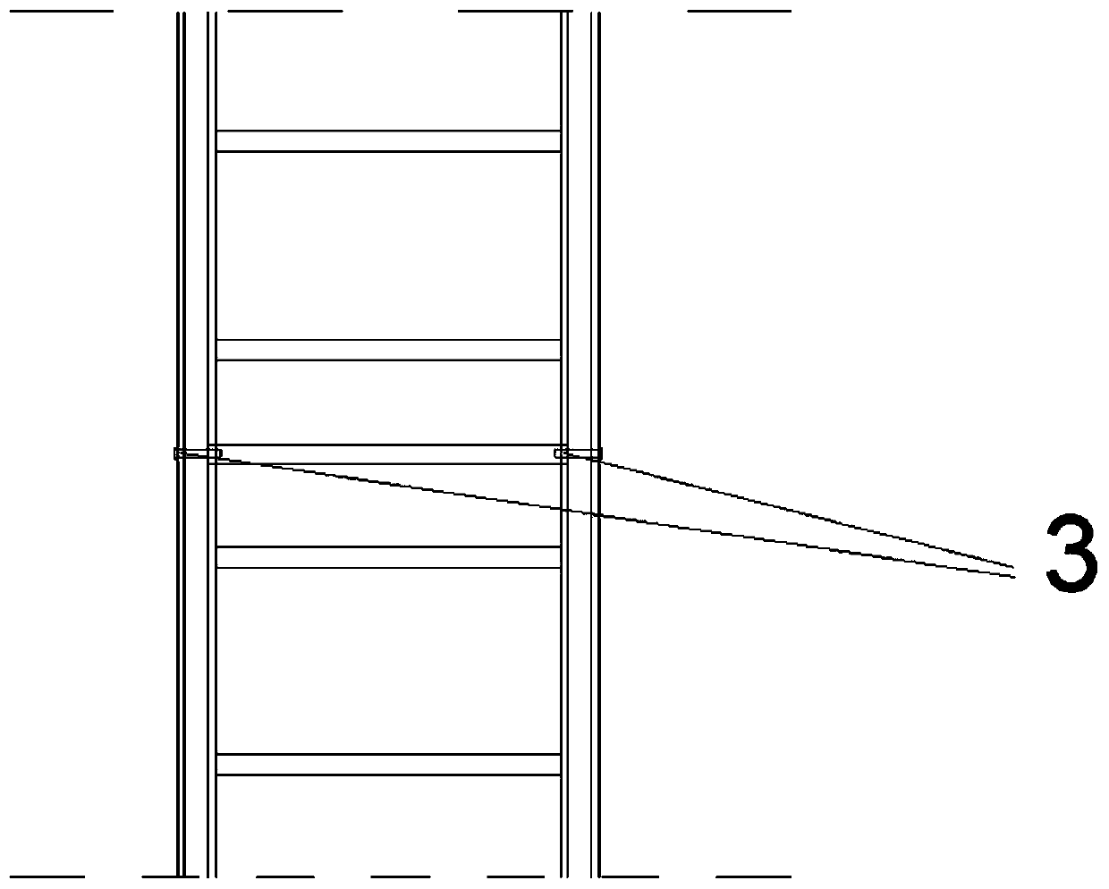
[0032] like figure 1 and figure 2 Shown, respectively, are the front view and side view of the overall ladder device. figure 2 It shows that the whole ladder device is installed in parallel with the shaft wall, and such a device and installation method can save the space between the segment and the shaft wall as much as possible. like figure 1 As shown in the figure, the pin shaft hole 3 is located on the step edge 1 in the middle part of the two cross bars ...


PUM


Abstract

The invention relates to a testing device capable of achieving up-and-down climbing in a counter-force well and turnover plate standing. The testing device comprises a main crawling ladder part, a crawling ladder moving plate and a supporting rod. The main crawling ladder part comprises ladder sides, cross rods and pin shaft holes. Hoisting holes and pin shaft holes are formed in the two sides ofthe crawling ladder moving plate. Inserting holes are formed in the two ends of the supporting rod, and the supporting rod is used for connecting the ladder sides with the crawling ladder moving plate. The main crawling ladder part is prefabricated and then is directly mounted on the inner wall of the counter-force well, a pin shaft hole is formed in the middle position of the part, between everytwo stages of cross rods, of the ladder sides, and two pin shaft holes form a pair. Pin shaft holes are formed in the four corners of the two sides of the crawling ladder moving plate. The testing device has the beneficial effects that the crawling ladder is mounted close to the wall of the counter-force well, personnel can climb conveniently, not too much space is occupied, and enough space is left for activities of testing personnel; and when the crawling ladder moving plate does not need to stand, pin shafts connecting the supporting rod with the ladder sides can be drawn out, the crawlingladder moving plate is attached to the crawling ladder, and space can also be saved.

Description

technical field [0001] The invention belongs to the technical field of tunnel engineering simulation test in geotechnical and underground engineering, and relates to a test device and method capable of climbing up and down and turning over to stand in a reaction well. Background technique [0002] With the development of society and the substantial increase of population, urban land resources are becoming increasingly tense. With the rapid development of urban infrastructure and the further development of underground space resources, rail transit has become an indispensable part of the bus system in large cities. Due to its advantages of green environmental protection, high degree of mechanization, and not being affected by climatic conditions, shield tunnels assembled on site with prefabricated segments have become an important structural form of municipal infrastructure such as urban rail transit today. [0003] However, during the construction and operation of shield tun...

Claims


Application Information

Patent Timeline
IPC IPC(8): E06C9/08
CPCE06C9/08
Inventor 魏纲周鑫鑫黄时雨刘亚宇张鑫海齐永洁戴子涵
Owner ZHEJIANG UNIV CITY COLLEGE
Why Eureka
Try Eureka