
Punching and cutoff mold for left support and right support of automobile

A punching and automobile technology, applied in the field of auto parts processing, can solve the problems of unfavorable large-scale production of the left and right brackets of the front beam of the car, increase the labor intensity of workers, and many processing procedures, so as to shorten the production cycle, facilitate production management, The effect of fewer molds

Inactive Publication Date: 2020-05-01
湖南忠元红快速充电有限公司
View PDF0 Cites 0 Cited by
  • Summary
  • Abstract
  • Description
  • Claims
  • Application Information

AI Technical Summary

Problems solved by technology

[0005] Aiming at the deficiencies of the prior art, the present invention provides a punching and cutting die for the left and right brackets of the automobile, which solves the problem that the holes on the left and right brackets of the front beam of the automobile in the prior art are stamped separately by stamping dies, and the left and right brackets are also separately punched. Formed, this kind of production process and mold making has many production processes, a large number of molds used, and many and scattered processing steps, which is not convenient for the production management of the left and right brackets of the front beam of the car, and also increases the labor intensity of the workers, and the production investment is large. , low production efficiency and high production cost, which is not conducive to the mass production of the left and right brackets of the front beam of the car

Method used


Image

  • Punching and cutoff mold for left support and right support of automobile
  • Punching and cutoff mold for left support and right support of automobile
  • Punching and cutoff mold for left support and right support of automobile

Examples


Embodiment 1

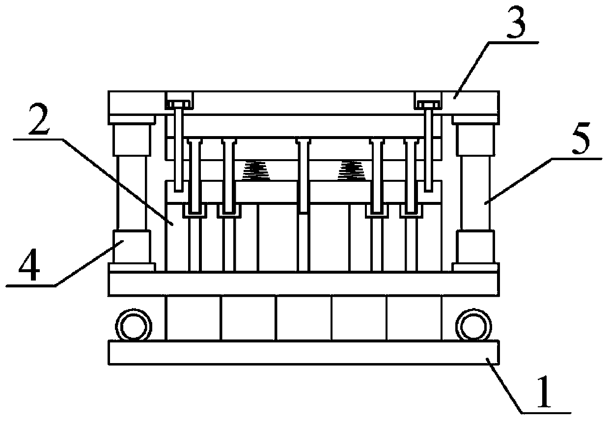
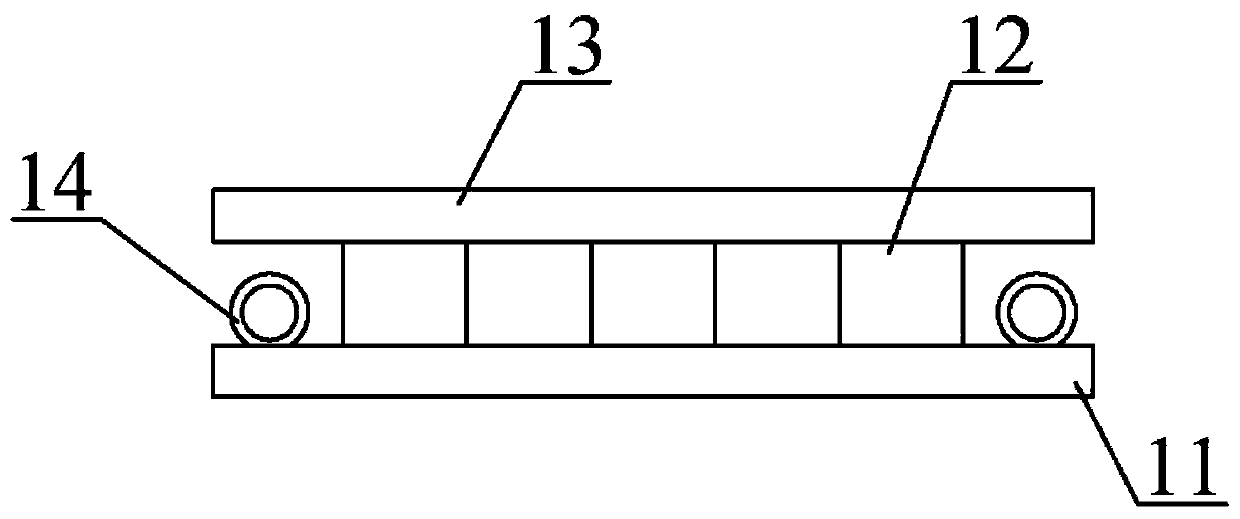
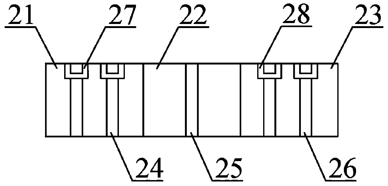
[0024] like Figure 1-4 As shown, the present invention provides a technical solution: a punching and cutting mold for the left and right brackets of automobiles, including a support mechanism, a lower mold mechanism, an upper mold mechanism, a guide sleeve and a guide column, and the lower mold mechanism is fixed on the support by bolts. The middle position above the mechanism; four guide sleeves are used, and the guide sleeves are fixed on the upper four corners of the support mechanism by bolts, and guide holes are opened on the inner side of the guide sleeves; the upper mold mechanism is arranged above the lower mold mechanism ; The guide column adopts four, and the guide column is fixed on the lower four corners of the upper die mechanism by bolts, and the lower end of the guide column is located inside the guide hole of the guide sleeve, wherein the size of the guide column matches the size of the guide sleeve; The support mechanism includes a lower footboard, a backing ...

Embodiment 2

[0026] A punching and cutting die for the left and right brackets of an automobile, comprising a support mechanism, a lower mold mechanism, an upper mold mechanism, a guide sleeve and a guide post, the lower mold mechanism is fixed at the middle position above the support mechanism by bolts; the guide sleeve Four are used, and the guide sleeve is fixed on the upper four corners of the support mechanism by bolts, and the inner side of the guide sleeve is provided with a guide hole; the upper mold mechanism is arranged above the lower mold mechanism; four guide columns are used, and The guide column is fixed on the lower four corners of the upper mold mechanism by bolts, and the lower end of the guide column is located inside the guide hole of the guide sleeve, wherein the size of the guide column matches the size of the guide sleeve; the supporting mechanism includes a lower foot plate, a backing plate, Lower die base and lifting lugs; four lifting lugs are used, and the lifting...

Embodiment 3

[0030] A punching and cutting die for the left and right brackets of an automobile, comprising a support mechanism, a lower mold mechanism, an upper mold mechanism, a guide sleeve and a guide post, the lower mold mechanism is fixed at the middle position above the support mechanism by bolts; the guide sleeve Four are used, and the guide sleeve is fixed on the upper four corners of the support mechanism by bolts, and the inner side of the guide sleeve is provided with a guide hole; the upper mold mechanism is arranged above the lower mold mechanism; four guide columns are used, and The guide column is fixed on the lower four corners of the upper mold mechanism by bolts, and the lower end of the guide column is located inside the guide hole of the guide sleeve, wherein the size of the guide column matches the size of the guide sleeve; the supporting mechanism includes a lower foot plate, a backing plate, Lower die base and lifting lugs; four lifting lugs are used, and the lifting...


PUM


Abstract

The invention discloses a punching and cutoff mold for a left support and a right support of an automobile. The punching and cutoff mold comprises a supporting mechanism, a lower mold mechanism, an upper mold mechanism, guide sleeves and guide columns. According to the punching and cutoff mold, through the arrangement of the upper mold mechanism and the lower mold mechanism, a left support blank and a right support blank are placed between the upper mold mechanism and the lower mold mechanism, and punching, cutoff and edge cutting work of the left support blank and the right support blank canbe achieved at the same time; the mold is adopted for doing machining work of the left support and the right support, few production procedures are needed, the number of adopted molds is small, production and management of the left support and the right support of an automobile front cross beam are convenient, the labor intensity of workers is reduced, the production period is shortened, and wideapplication and popularization value is achieved in the industry; through the arrangement of the supporting mechanism, a lower mold seat achieves a supporting function on the lower mold mechanism, itis guaranteed that the lower mold mechanism is placed stably, and lifting of the lower mold mechanism can be achieved conveniently through lifting lugs; and the machining efficiency of the left support and the right support is improved, the production input is small, production cost is low, and large-scale production of the left support and the right support of the automobile front cross beam is facilitated.

Description

technical field [0001] The invention relates to the technical field of auto parts processing, in particular to a punching and cutting die for left and right brackets of an automobile. Background technique [0002] At present, the holes on the left and right brackets of the front beam of the car are stamped separately by stamping dies, and the left and right brackets are also formed separately. This production process and mold production require many production processes and a large number of molds. Many and scattered, it is not convenient for the production management of the left and right brackets of the front beam of the car, and it also increases the labor intensity of the workers. It is urgent to develop a punching and cutting die for the left and right brackets of the car to solve the above problems and facilitate market promotion and application. [0003] In the prior art, the holes on the left and right brackets of the front beam of the automobile are stamped separate...

Claims


Application Information

Patent Timeline
Patent Type & Authority Applications(China)
IPC IPC(8): B21D37/08B21D35/00B21D28/02B21D28/24B21D53/88
CPCB21D28/02B21D28/24B21D35/001B21D37/08B21D53/88
Inventor 贺士忠
Owner 湖南忠元红快速充电有限公司
Learn More