
An electrically driven motor base adjuster

A motor base and electric drive technology, applied in the direction of electric components, electrical components, electromechanical devices, etc., can solve the problem of damage to the service life of auxiliary structures such as motors and belts, the difficulty of ensuring the stability of the movable base support, and the stability of the motor base support. Contribution and other issues to achieve the effect of reducing acquisition cost, increasing slack, and reducing performance requirements

Active Publication Date: 2020-08-25
大庆强弘科技有限公司
View PDF7 Cites 0 Cited by
  • Summary
  • Abstract
  • Description
  • Claims
  • Application Information

AI Technical Summary

Problems solved by technology

[0003] After searching, there are already some motor bases that can fine-tune the motor position in other fields, but these motor base products are all used in the way of horizontal adjustment. If it is applied to the beam pumping unit, the gravity of the motor itself will It cannot contribute to the support stability of the motor base, which makes it difficult to guarantee the support stability of the movable base, resulting in loud noise and severe vibration during the working process of the motor, which seriously damages the service life of the motor and auxiliary structures such as belts

Method used


Image

  • An electrically driven motor base adjuster
  • An electrically driven motor base adjuster
  • An electrically driven motor base adjuster

Examples


Embodiment Construction

[0034] The present invention will be further described below in conjunction with accompanying drawing:

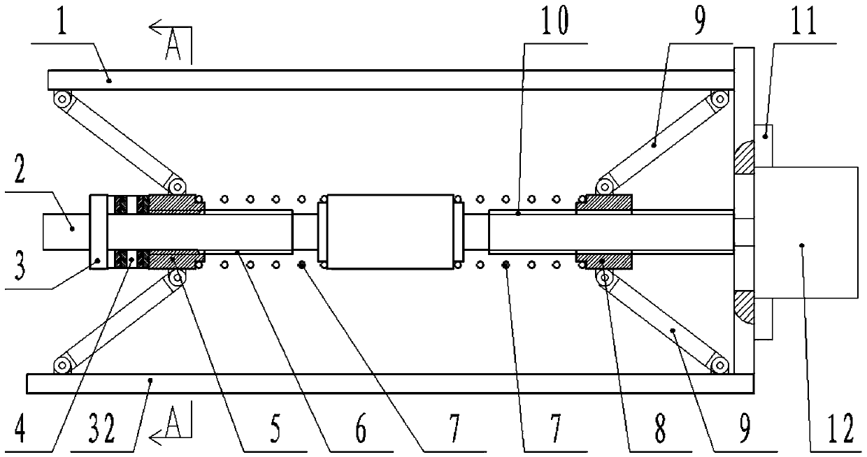
[0035] This embodiment includes an upper plate 1 and a lower plate 32, a drive mechanism is arranged between the upper plate 1 and the lower plate 32, and the upper plate 1 and the lower plate 32 move relatively under the action of the drive mechanism, thereby realizing the motor 20 of the pumping unit. Position adjustments. The above are existing structures in the prior art, and will not be repeated here.

[0036] The important innovation of the present invention is that: the driving mechanism between the upper plate 1 and the lower plate 32 is a lifting mechanism.

[0037] Most of the main drive belts on the existing beam pumping units are inclined, so the motor 20 of the pumping unit can adjust the tension of the belt by moving laterally and vertically. However, since the motor 20 of the pumping unit The self-weight of the self-weight can reach hundreds of kilograms us...


PUM


Abstract

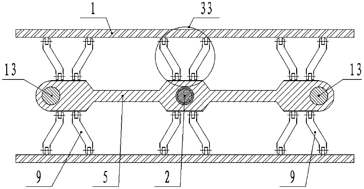
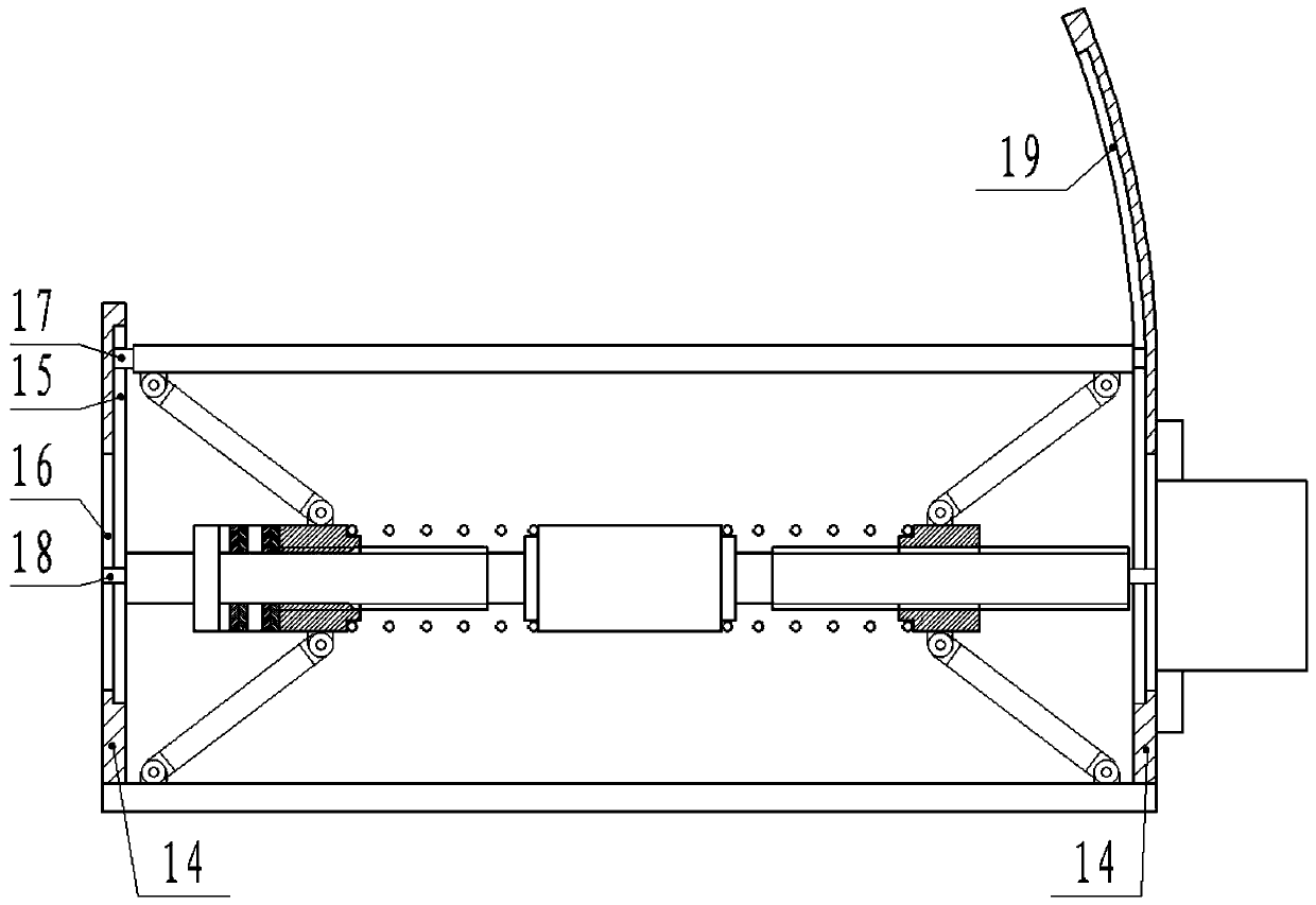
The invention belongs to the field of pumping unit accessory equipment, and particularly relates to an electrically-driven motor base adjuster which comprises an upper plate and a lower plate, a driving mechanism is arranged between the upper plate and the lower plate, and the driving mechanism between the upper plate and the lower plate is a lifting mechanism. The lifting mechanism structurally comprises a driving shaft, a connecting body A, a connecting body B and a connecting rod, the connecting body A and the connecting body B are respectively connected to the outer sides of the left-handthread section and the right-hand thread section through threads; the connecting body A and the upper plate, the connecting body A and the lower plate, the connecting body B and the upper plate, and the connecting body B and the lower plate are connected through the connecting rods respectively; and the connecting rods form a space truss structure with a triangular unit between the upper plate andthe lower plate. According to the invention, the multi-connected truss structure with a plurality of triangular units is arranged, so that the motor of the oil pumping unit is stably supported whileascending and descending, and meanwhile, the motion precision in the ascending and descending process is ensured.

Description

technical field [0001] The invention belongs to the field of auxiliary equipment of pumping units, in particular to an electrically driven motor base adjuster. Background technique [0002] In my country's petroleum industry production, the beam pumping unit is a mainstream oil production equipment. The beam pumping unit is equipped with a high-power motor and a reducer, and the power connection between the motor and the reducer is realized through a belt and a pulley. The belt will loosen slightly after being used for a period of time under heavy load conditions, resulting in accelerated belt wear, shortened belt life, and reduced mechanical efficiency. In addition, in the cold areas of northern my country, the temperature difference between winter and summer is large, and the belt is more likely to loosen under the action of thermal expansion and contraction. Therefore, workers often need to fine-tune the installation position of the motor. [0003] After searching, the...

Claims


Application Information

Patent Timeline
Patent Type & Authority Patents(China)
IPC IPC(8): H02K5/26H02K7/10
CPCH02K5/26H02K7/10H02K7/1004
Inventor 魏良艳
Owner 大庆强弘科技有限公司
Learn More