
Cable eccentricity detection device

A detection device and eccentricity technology, applied in the direction of measuring device, using electrical device, using electromagnetic means, etc., can solve the problems of material waste, damage, breakdown, safety hazard, etc., and achieve the effect of high efficiency and small frictional resistance

Active Publication Date: 2020-04-28
ANHUI FUXING CABLE GRP
View PDF9 Cites 4 Cited by
  • Summary
  • Abstract
  • Description
  • Claims
  • Application Information

AI Technical Summary

Problems solved by technology

[0002] In the quality problems of cable products, the eccentricity of the core wire in the cable manufacturing process is an important factor affecting the quality of the cable. After a long period of use, the mechanical resistance and chemical resistance of the thinner point must be weaker, and damage, breakdown, wear, and exposure will occur earlier, causing damage to the cable, which will affect normal use and bring safety hazards , in view of this problem, the traditional cable eccentricity detection method mainly relies on manual stripping and cutting of the cable, and then uses a caliper to manually measure or use an optical instrument to measure the thickness of the cable cross section to obtain the cable eccentricity. Both calipers and optical instruments have the following problems. On the one hand, more manual participation is required, the measurement error is large, and the operation is inconvenient and time-consuming. On the other hand, the cable eccentricity cannot be detected online in real time during the production process, so that The deviation of cable eccentricity cannot be monitored online, which will easily cause waste of materials and even produce unqualified products

Method used


Image

  • Cable eccentricity detection device
  • Cable eccentricity detection device
  • Cable eccentricity detection device

Examples


Embodiment Construction

[0031] In order to make the objectives, technical solutions, and advantages of the present invention clearer, the following further describes the present invention in detail with reference to specific embodiments and drawings.

[0032] It should be noted that all the expressions "first" and "second" in the embodiments of the present invention are used to distinguish two entities with the same name but not the same or parameters that are not the same, as shown in "first" and "second" Only for the convenience of presentation, it should not be construed as a limitation to the embodiments of the present invention, and subsequent embodiments will not describe this one by one.

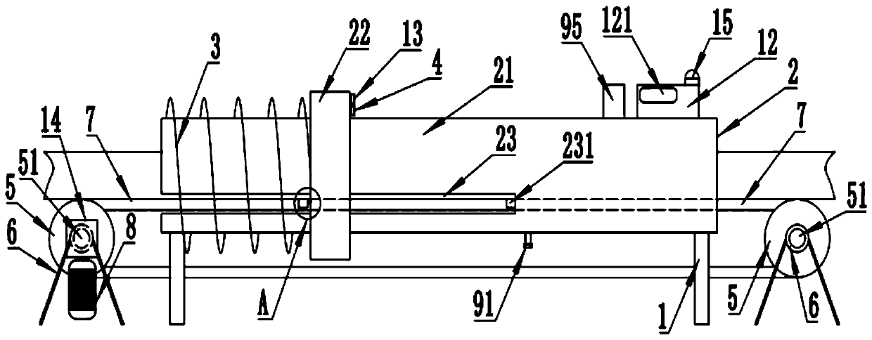
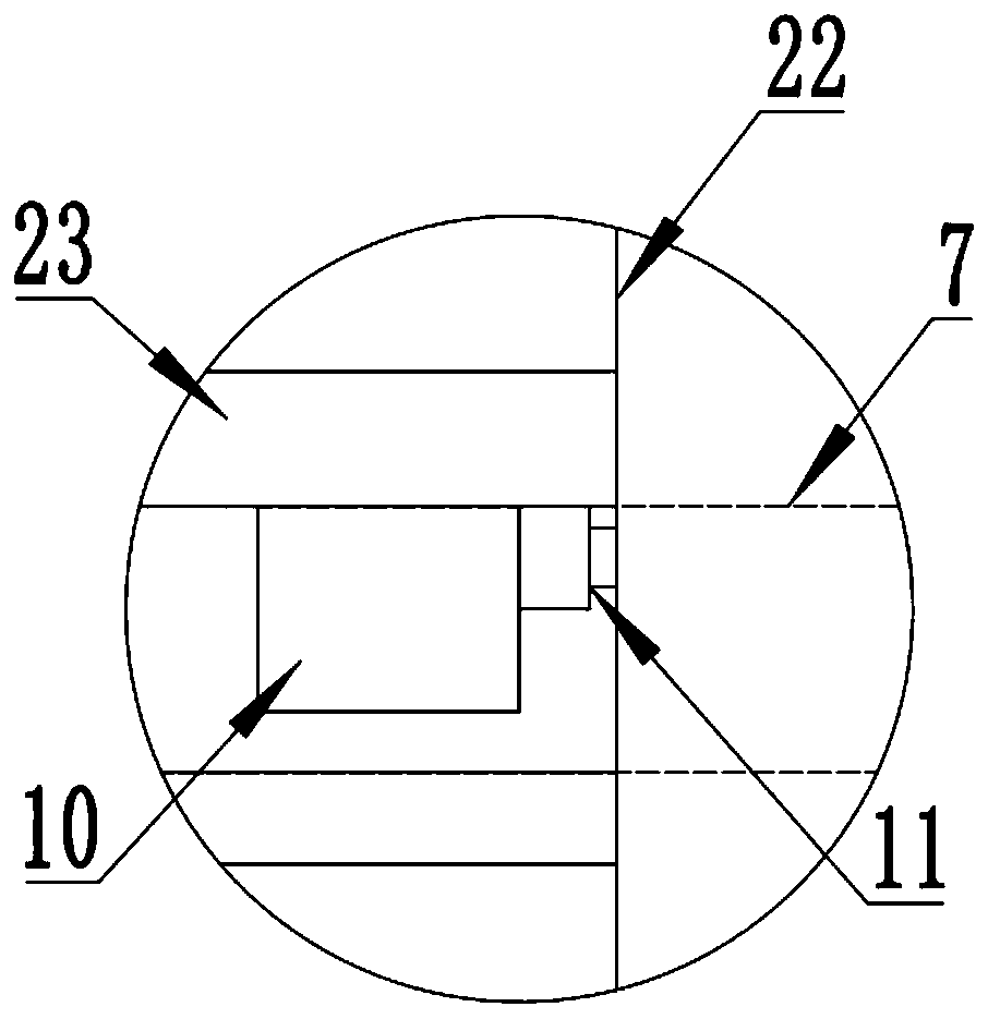
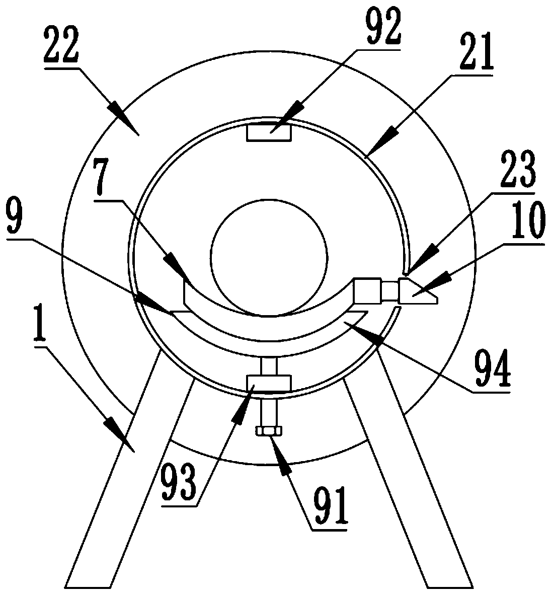
[0033] A cable eccentricity detection device, such as Figure 1 to Figure 3 As shown, the bracket 1 is included. The ball screw 2 includes a screw 21 and a nut 22. Both ends of the screw 21 are fixedly erected on the bracket 1. The screw 21 is a hollow structure. The side wall of the screw 21 is provided with a t...


PUM


Abstract

The invention discloses a cable eccentricity detection device comprising a screw rod and a nut. Two ends of the screw rod are fixedly erected on a bracket; an eddy current sensor is fixed on the nut;belt wheels are arranged below the two ends of the screw rod; and a conveying belt is wound on the belt wheels in a tensioning manner. A motor can drive the conveyor belt to convey the cable in the screw rod; a spring ejector rod rotates along with the conveying belt and can pass through a through hole formed in one end of the screw rod and push the nut to slide simultaneously; a touch switch is trigger simultaneously to trigger an eddy current sensor; the eccentricity degree of the cable core can be reflected through a range value, measured by the eddy current sensor, of the displacement signal of the cable core. The spring ejector rod is pushed by a flange to retract into the screw rod, so that the nut slides and resets under the effect of the spring. A processor is arranged and is usedfor receiving a displacement signal measured by the eddy current sensor and calculating the range value of the displacement signal; and the processor is further provided with a display screen for displaying the range value so as to achieve the function of non-destructive on-line real-time automatic detection of the eccentricity of the cable.

Description

Technical field [0001] The invention relates to the technical field of cable processing equipment, in particular to a cable eccentricity detection device. Background technique [0002] In the quality of cable products, the eccentricity of the core wire in the cable manufacturing process is an important factor affecting the quality of the cable. The eccentricity of the core wire means that the conductive core of the cable is not concentric with the insulation layer, which makes the insulation thickness of the cable cross section different. After the use of time, the resistance to mechanical and chemical substances at the thinner points is definitely weak, and breakage, breakdown, abrasion, exposure, and damage to the cable will occur earlier, which will affect normal use and bring safety hazards. In response to this problem, the traditional cable eccentricity detection method mainly relies on manually stripping the cable, and then manually measuring the thickness of the cable cros...

Claims


Application Information

Patent Timeline
Patent Type & Authority Applications(China)
IPC IPC(8): G01B7/312
CPCG01B7/312
Inventor 居盛文童天明方伟谷庆生吴云
Owner ANHUI FUXING CABLE GRP
Learn More