Sewage treatment device for environmental engineering

A technology of sewage treatment equipment and environmental engineering, applied in water/sewage treatment, heating water/sewage treatment, water/sewage treatment equipment, etc., can solve the problems of filter plate clogging and low filtration efficiency, etc.

Inactive Publication Date: 2020-04-28
南京瑞碧斯生物科技有限公司
View PDF0 Cites 2 Cited by
  • Summary
  • Abstract
  • Description
  • Claims
  • Application Information

AI Technical Summary

Problems solved by technology

[0003] Nowadays, when the sewage containing sediment is treated, it is often only treated by filtration, but at present, the filter plate is used as the filter device. When the water passes through the filter plate, the filter plate is often blocked, and manual operation is required. Cleaning makes the filtration efficiency low, so we propose a sewage treatment device for environmental engineering to solve the above-mentioned problems

Method used


Image

  • Sewage treatment device for environmental engineering
  • Sewage treatment device for environmental engineering
  • Sewage treatment device for environmental engineering

Examples


Embodiment 1

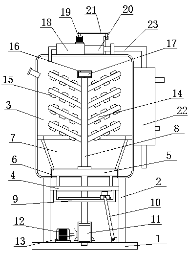
[0032] see Figure 1-5 , this embodiment provides a sewage treatment device for environmental engineering, including a base 1, two uprights 2 are symmetrically fixedly installed on the top of the base 1, and the same evaporation box 3 is fixedly installed on the top of the two uprights 2, two The sides of the columns 2 close to each other are slidably connected with the same moving plate 4, the top of the moving plate 4 is fixedly equipped with a sealing plate 5, the bottom inner wall of the evaporation box 3 is fixedly installed with a sealing ring 6, and the bottom inner wall of the evaporation box 3 is provided with a There is a moving hole, the top of the sealing plate 5 extends into the sealing ring 6 and seals with the inner wall of the sealing ring 6, the sealing plate 5 is rotatably connected with a rotating shaft 8, and the bottom end of the rotating shaft 8 extends to the bottom of the moving plate 4, and the rotating shaft 8 is equipped with a stirring mechanism, th...

Embodiment 2

[0036] see Figure 1-5 , further improvements have been made on the basis of Example 1:

[0037] In this embodiment, a mounting plate 9 is fixedly mounted on one side of the bottom of the moving plate 4, and a slide plate 31 is slidably connected to the top of the mounting plate 9, and a brake motor 32 is fixedly mounted on the top of the slide plate 31. The output shaft of the brake motor 32 A transmission gear 33 is fixedly installed on the top, and a transmission rack 34 is fixedly installed on the bottom of the moving plate 4. The transmission gear 33 is meshed with the transmission rack 34. One side of the slide plate 31 is rotatably connected with a support rod 10, and one end of the support rod 10 is connected to the One side of the top of the base 1 is rotationally connected, and the support rod 8 can be driven to rotate by using the brake motor 32, the transmission gear 33 and the transmission rack 34.

[0038] In this embodiment, the stirring mechanism includes a pl...


PUM


Abstract

The invention discloses a sewage treatment device for environmental engineering. The sewage treatment device comprises a base. Two stand columns are symmetrically and fixedly mounted at the top of thebase; the same evaporation box is fixedly mounted at the top ends of the two stand columns; the sides, close to each other, of the two stand columns are slidably connected with the same moving plate.A sealing plate is fixedly installed at the top of the moving plate, a sealing ring is fixedly installed on the inner wall of the bottom of the evaporation box, a moving hole is formed in the inner wall of the bottom of the evaporation box, and the top of the sealing plate extends into the sealing ring and is attached to the inner wall of the sealing ring in a sealed mode. The evaporation principle is utilized, water can be heated into gas to be separated from silt, and steam can be quickly cooled to form liquid water under the action of condensation so that existing filtering equipment is not needed for filtering in use, the silt can be thoroughly separated from the water, and the device is very convenient to use.

Description

technical field [0001] The invention relates to the technical field related to the hoisting of industrial barrels, in particular to a sewage treatment device for environmental engineering. Background technique [0002] Sewage treatment is the process of purifying sewage to meet the water quality requirements for drainage or reuse. Sewage treatment is widely used in construction, agriculture, transportation, energy, petrochemical, environmental protection, urban landscape, medical treatment, catering, etc. field, and more and more into the daily life of ordinary people. [0003] Nowadays, when the sewage containing sediment is treated, it is often only treated by filtration, but at present, the filter plate is used as the filter device. When the water passes through the filter plate, the filter plate is often blocked, and manual operation is required. Cleaning makes the filtration efficiency low, so we propose a sewage treatment device for environmental engineering to solve ...

Claims


Application Information

Patent Timeline
Patent Type & Authority Applications(China)
IPC IPC(8): C02F1/04
CPCC02F1/04C02F2201/002
Inventor 杨秀华王婷韩健宝彭兵
Owner 南京瑞碧斯生物科技有限公司
Why Eureka
Try Eureka