Eureka AIR delivers breakthrough ideas for toughest innovation challenges, trusted by R&D personnel around the world.

Injection or injection-compression molding tool and process for thermal insulation layer of combustion chamber of solid rocket engine

A solid rocket, injection molding technology, applied in the coating and other directions, can solve the problems of low dimensional accuracy of forming shape, difficult dimensional structure operation, low one-time pass rate, etc., to achieve high quality consistency and stability, eliminate stickiness Influence factors of bonding agent, effect of fast glue injection

Active Publication Date: 2020-04-28
HUBEI INST OF AEROSPACE CHEMOTECHNOLOGY
View PDF11 Cites 4 Cited by
  • Summary
  • Abstract
  • Description
  • Claims
  • Application Information

AI Technical Summary

Problems solved by technology

[0003] Generally, the thermal insulation layer of the combustion chamber of small and medium-sized solid rocket motors is usually formed by prefabricating the parts and pasting them on the inner wall of the prepared shell by hand, and then adopting the airbag pressurization of the cavity in a vacuum state or the pressurization of a tooling mold that can be realized. At present, It is the mainstream airbag pressurization process that requires highly skilled operators, but the accuracy of the shape and size of the molding is not high, the efficiency is low, and the first pass rate is not high, and the molding of the tooling mold is also limited by size, structure, and expansion after loading. Difficult process operation has limitations

Method used


Image

  • Injection or injection-compression molding tool and process for thermal insulation layer of combustion chamber of solid rocket engine
  • Injection or injection-compression molding tool and process for thermal insulation layer of combustion chamber of solid rocket engine
  • Injection or injection-compression molding tool and process for thermal insulation layer of combustion chamber of solid rocket engine

Examples


Embodiment 1

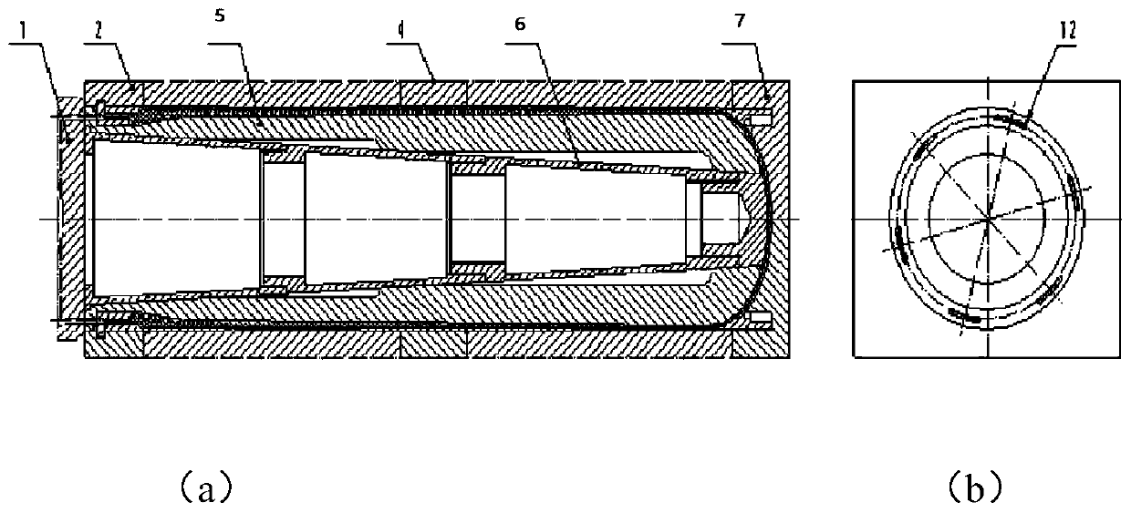
[0041] When the insulating casing is vertical, the structure of the injection molding tooling for the thermal insulation layer of the solid rocket motor combustion chamber is as follows: figure 1 As shown in (a), it includes a pouring integrated plate 1, a heat-insulating shell pressure-bearing limit assembly, a split-type combined mold core 5, a limit cone 6, and a heat-insulating shell. The detailed design of each part is as follows:

[0042] The pressure-bearing limit assembly of the heat-insulated shell is used to provide pressure-bearing support for the outside of the heat-insulated shell during the process of injecting or pressing the heat-insulating material inside the heat-insulated shell; it includes a plurality of heat-insulated shell limit pressure-bearing blocks 2, 7, 8, 9, 10, the inner side of these limit bearing blocks of the heat insulating shell are sintered with polytetrafluoroethylene coating, the thickness of the polytetrafluoroethylene coating is 0.05mm ~ 0...

Embodiment 2

[0048] When the heat insulation casing is horizontal, the structure of the injection molding tooling for the heat insulation layer of the solid rocket motor combustor is as follows: figure 2 As shown in (a), it is basically the same as that of Embodiment 1. The pouring integrated board 1 is on the side of the heat-insulating shell. From the left sectional view, the distribution of the runners 12 on the pouring integrated board 1 is as follows figure 2 As shown in (b), a plurality of heat-insulating shell space-limiting pressure-bearing blocks 2, 4, 7 of the heat-insulating shell pressure-limiting assembly protect the heat-insulating shell from the periphery; From the port on one side of the heat-insulating shell, enter the cavity inside the heat-insulating shell where the molding and the heat-insulating shell form an insulating layer.

[0049] The molding process adopts a high-pressure injection method, and the heat-insulating material is injected into the cavity between the...

Embodiment 3

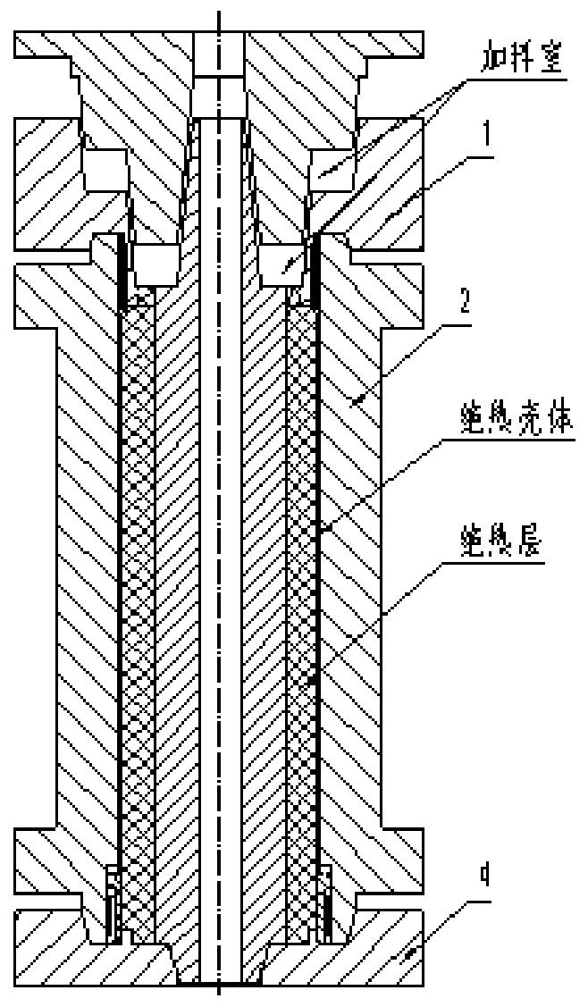
[0051] When the heat insulation shell is a vertical heat insulation shell with its own feeding chamber, the structure of the injection molding tooling for the heat insulation layer of the solid rocket motor combustion chamber is as follows: image 3 As shown, it is basically the same as Example 1, the difference is that the tooling mold has its own feeding chamber, which can be implemented when there is no pressurization or injection function on the equipment, and is generally suitable for heat insulation of small or micro engines

[0052] The molding process adopts the injection pressure method, and the heat insulating material is injected into the cavity between the heat insulating shell and the split-type combined mold core 5 with a pressure of 3Mpa-20MPa. The schematic diagram of the heat insulating material formed in the heat insulating shell is as follows: Figure 8 shown.

[0053] In the above-mentioned examples 1-3, in order to ensure that compared with ordinary rubbe...


PUM

PropertyMeasurementUnit
thicknessaaaaaaaaaa

Abstract

The invention belongs to the technical field of manufacturing of thermal insulation layers in thermal protection structures of solid rocket engines, and provides an injection or injection-compressionmolding tool for a thermal insulation layer of a combustion chamber of a solid rocket engine. The injection or injection-compression molding tool comprises a pouring integrated plate (1), a thermal insulation shell pressure-bearing limiting assembly, a split-type combined mold core (5), a limiting cone (6) and a thermal insulation shell; the thermal insulation shell pressure-bearing limiting assembly is used for providing pressure-bearing support for the outer side of the thermal insulation shell in the process of injection or injection-compression of a thermal insulation material into the thermal insulation shell; the split-type combined mold core (5) and the limiting cone (6) are matched to be placed in the thermal insulation shell and form a cavity with the thermal insulation shell, andthe cavity is consistent with the thermal insulation layer to be subjected to injection or injection-compression molding in shape and size so as to allow the thermal insulation material to be injected in a pressurized mode at the high pressure; and a thermal insulation material injecting channel is formed in the pouring integrated plate (1), so that the thermal insulation material enters the cavity among the thermal insulation shell, the split-type combined mold core and the limiting cone through the pouring integrated plate (1).

Description

technical field [0001] The invention belongs to the technical field of heat-insulating layer manufacturing for thermal protection structures of solid rocket motors, and in particular relates to an injection or pressure-injection molding tool and technology for making a solid rocket motor combustion chamber heat-insulating layer. Background technique [0002] Solid rocket motor is one of the most important power sources configured in various missile weapons and equipment. As an important component, the high-quality, high-efficiency, and low-cost molding of the combustion chamber insulation layer has always been the bottleneck in the manufacturing process. With the traction of manufacturing quantity, high performance, high efficiency, and low cost requirements, it is becoming more and more difficult to adapt to its development needs by using traditional molding methods. [0003] Generally, the thermal insulation layer of the combustion chamber of small and medium-sized solid r...

Claims


Application Information

Patent Timeline
Patent Type & Authority Applications(China)
IPC IPC(8): B29C45/14B29C45/26B29C45/27
CPCB29C45/14B29C45/14065B29C45/26B29C45/27
Inventor 彭正贵王江詹穹胡俊杰孙笑然李洋伍政彭琴李月常陈亚格
Owner HUBEI INST OF AEROSPACE CHEMOTECHNOLOGY
Why Eureka
Eureka Blog
Learn More