
Automatic cleaning mechanism for photovoltaic power generation panel

A technology of automatic cleaning and photovoltaic power generation, applied in photovoltaic power generation, cleaning methods using tools, cleaning methods using liquids, etc., can solve the problems of lack of renewable energy, heavy workload, low cleaning efficiency, etc., to achieve long-term benefits Long-term use, improved service life, and improved lubricity

Inactive Publication Date: 2020-04-28
兰杰
View PDF13 Cites 3 Cited by
  • Summary
  • Abstract
  • Description
  • Claims
  • Application Information

AI Technical Summary

Problems solved by technology

[0002] At present, with the continuous progress and development of science and technology, the renewable energy continues to be scarce. People begin to look for new energy to replace the non-renewable energy. Photovoltaic power generation uses solar panels to convert light energy into electrical energy, which can continuously convert renewable energy. The energy for use, and it can be said to be zero pollution and zero emission to the environment. It is the current mainstream power generation method in society, but the photovoltaic power generation system also has certain defects. First, the efficiency of energy conversion is not high, and second, it is too affected by the weather. At the same time, the photovoltaic base station is a combination of a large number of photovoltaic panels to generate electricity, and the surface of the photovoltaic panel is also prone to dust, resulting in a lower conversion efficiency of the photovoltaic panel. The traditional processing method is to clean the rice panels manually on a regular basis, but the workload is too large, the cleaning efficiency is too low, and it is very inconvenient. At present, there is no automatic cleaning equipment to solve the problem of photovoltaic panel cleaning. In order to solve the above-mentioned problems, we propose an automatic cleaning for photovoltaic panels. mechanism

Method used


Image

  • Automatic cleaning mechanism for photovoltaic power generation panel
  • Automatic cleaning mechanism for photovoltaic power generation panel
  • Automatic cleaning mechanism for photovoltaic power generation panel

Examples


Embodiment Construction

[0028] The following will clearly and completely describe the technical solutions in the embodiments of the present invention with reference to the accompanying drawings in the embodiments of the present invention. Obviously, the described embodiments are only some, not all, embodiments of the present invention.

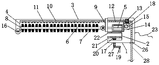
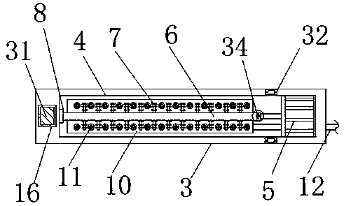
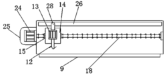
[0029] refer to Figure 1-5 , an automatic cleaning mechanism for photovoltaic power generation panels, including a casing 1, a dust removal cover 3, an infusion plate 10, an atomizing head 11, and a photovoltaic panel 30; the left side of the casing 1 is provided with a chute 9 and a clamping groove 2, and the chute 9 is located at the upper end of the clamping groove 2, the chute 9 has a built-in dust removal cover 3, and the bottom end of the dust removal cover 3 is provided with a cleaning groove 4, and the right end of the cleaning groove 4 is provided with a first motor 5, And the end of the motor shaft of the first motor 5 is provided with a rotating rod 6, th...


PUM


Abstract

The invention relates to an automatic cleaning mechanism. The following scheme is provided: the automatic cleaning mechanism comprises a casing, a dust removing cover, an infusion plate, atomizing heads and the photovoltaic panel, wherein a sliding groove and a clamping groove are formed in the left side of the casing, the sliding groove is located at the upper end of the clamping groove, the dustremoving cover is arranged in the sliding groove, a cleaning groove is formed in the bottom end of the dust removing cover, a first motor is arranged at the right end in the cleaning groove, a rotating rod is arranged at the tail end of a motor shaft of the first motor, brushes are wrapped on the outer wall of the rotating rod, the infusion plate is fixed at the top in the cleaning groove, and the atomizing heads are arranged at the bottom end of the infusion plate. The outer wall of the rotating rod is wrapped and connected with the brushes, the brushes are attached to the surface of the photovoltaic panel, the top end inside the cleaning groove is provided with the plurality of groups of atomizing heads, the brushes are driven by a rotating mechanism to rotate so that the brushes can brush the photovoltaic panel, and the cleaning effect is achieved. Meanwhile, a moving mechanism drives the dust removing cover to move based on the photovoltaic panel, and a comprehensive automatic cleaning effect is achieved.

Description

technical field [0001] The invention relates to an automatic cleaning mechanism, in particular to an automatic cleaning mechanism for a photovoltaic power generation panel. Background technique [0002] At present, with the continuous progress and development of science and technology, the renewable energy continues to be scarce. People begin to look for new energy to replace the non-renewable energy. Photovoltaic power generation uses solar panels to convert light energy into electrical energy, which can continuously convert renewable energy. The energy for use, and it can be said to be zero pollution and zero emission to the environment. It is the current mainstream power generation method in society, but the photovoltaic power generation system also has certain defects. First, the efficiency of energy conversion is not high, and second, it is too affected by the weather. At the same time, the photovoltaic base station is a combination of a large number of photovoltaic pan...

Claims


Application Information

Patent Timeline
Patent Type & Authority Applications(China)
IPC IPC(8): B08B1/04B08B3/02H02S40/10
CPCH02S40/10B08B1/50B08B1/32Y02E10/50
Inventor 兰杰
Owner 兰杰
Learn More