Method and device for optical surface measurement by means of a confocal sensor

An optical measurement and sensor technology, applied in the field of confocal sensors, can solve the problem that the readout speed cannot be further improved easily

Inactive Publication Date: 2020-04-24
NANOFOCUS
View PDF6 Cites 2 Cited by
  • Summary
  • Abstract
  • Description
  • Claims
  • Application Information

AI Technical Summary

Problems solved by technology

However, the readout speed of a spectrometer row has its limit in the range of a few kHz and cannot be easily increased further

Method used


Image

  • Method and device for optical surface measurement by means of a confocal sensor
  • Method and device for optical surface measurement by means of a confocal sensor

Examples


Embodiment Construction

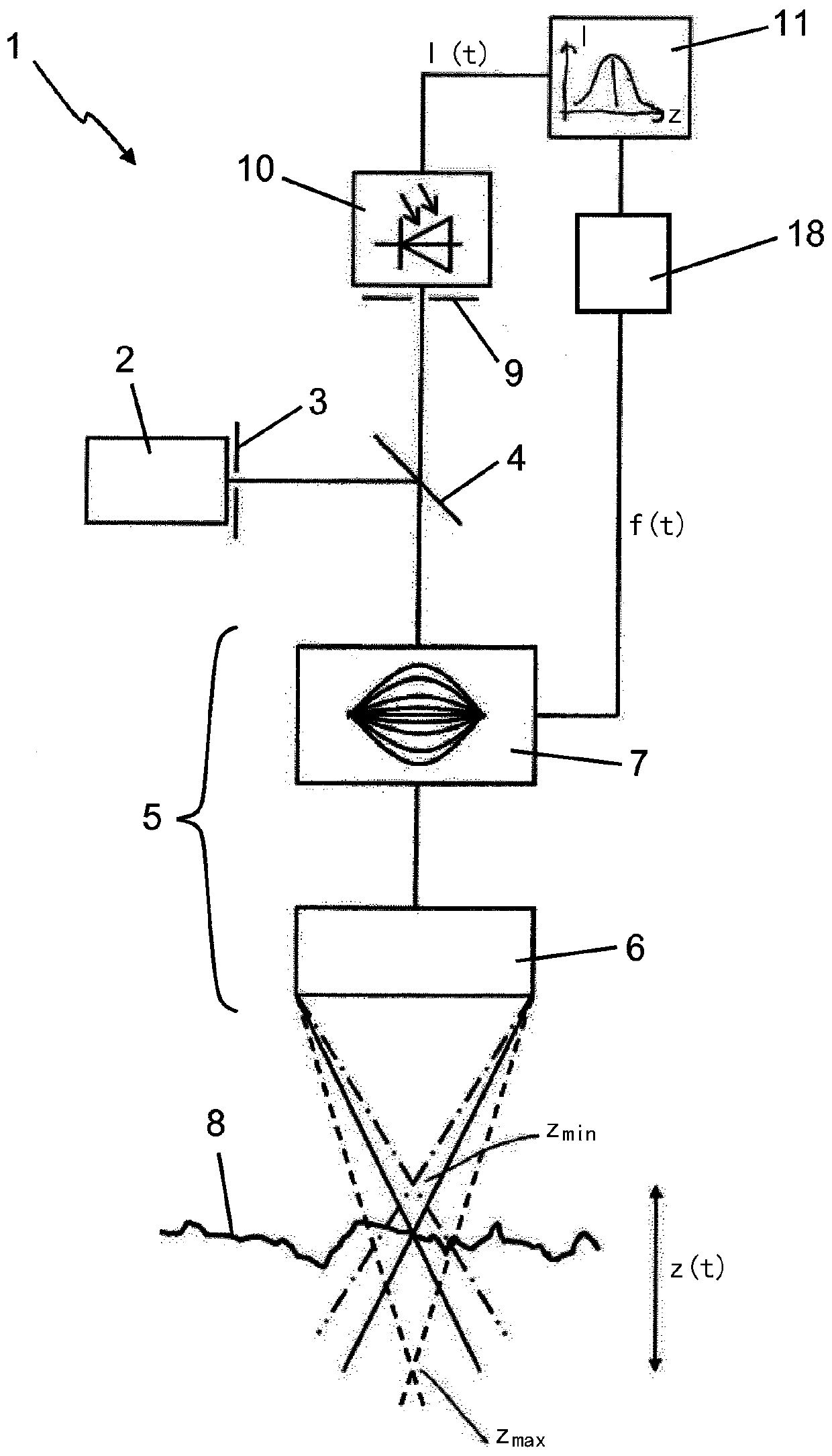
[0034] exist figure 1 A confocal sensor is shown in and is collectively assigned the reference number 1 . An essential component of such a confocal sensor 1 is, on the one hand, the light source, preferably a suitable laser, provided with the reference numeral 2 . A laser 2 sends its light through a confocal filter (pinhole) 3 to an optical system 5 via a beam splitter 4 (in the present embodiment, a semi-transparent mirror), which The optical system consists of objective lens 6 and TAG lens 7. The TAG lens is acted upon by means of an electrical signal f(t) generated by a function generator 18 . This leads to the fact that in the light-transmissive material of the TAG lens 7, due to the acousto-optic effect, the radial profile of the refractive index n versus the electrical signal is a function of time. The light is thus focused at different heights in the Z direction corresponding to the signal f(t) and directed at the sample 8 drawn. The focus position is preferably per...


PUM


Abstract

The invention relates to a method and a device for the optical measurement of technical surfaces by means of a confocal sensor, where light from a light source (2) is directed towards the surface (8)of a sample to be measured by means of an optical system (5, 16). According to the invention, the optical system (5, 16) comprises an electrically controlled adaptive optics (7), wherein the focus ofthe optical system (5, 16) is varied by an electric signal (f (t)) in the Z-direction. The light reflected back from the sample surface (8) is directed to at least one photosensor (10), where the sensor signal is measured over time by means of a detection device (11) and the time of a signal maximum is determined. The detection device (11) derives the height Z of the surface (8) from the electricsignal at the time of the signal maximum.

Description

technical field [0001] The invention relates to a method for optical measurement of technical surfaces by means of a confocal sensor, in which the light of at least one light source is directed through an optical system at the surface of a sample to be measured. [0002] The invention also relates to a confocal sensor for carrying out the method, which has at least one light source, the light of which is directed via an optical system to the surface of the sample to be measured. Background technique [0003] In confocal measurement techniques, light from a light source is usually focused on the surface to be measured by means of confocal filters, beam splitters and optical systems. In this case, in the prior art, either the measuring table on which the sample is located is moved up and down in the Z direction, however, or the optical system is moved and the exact moment at which the focal point collides with the onto the surface to be measured. This light is directed to th...

Claims


Application Information

Patent Timeline
Patent Type & Authority Applications(China)
IPC IPC(8): G01B11/24
CPCG01B11/0608G01B11/24
Inventor J·弗兰克G·雅各布
Owner NANOFOCUS
Why Eureka
Try Eureka