
Counter jig for high-speed electroplating production line

A high-speed electroplating and counter technology, applied in counting mechanisms/items, instruments, etc., can solve the problems of increasing equipment manufacturing costs, small terminal spacing, and high requirements for optical fiber counting sensitivity, and achieve the effect of reducing calibration work.

Pending Publication Date: 2020-04-24
KUNSHAN SOKAY AUTOMATION TECH CO LTD
View PDF0 Cites 0 Cited by
  • Summary
  • Abstract
  • Description
  • Claims
  • Application Information

AI Technical Summary

Problems solved by technology

[0003] Shells, terminals, and plates are produced as strip-shaped materials during electroplating for continuous production, and strip-shaped materials are usually transported by traction in order to facilitate continuous electroplating during electroplating. In the continuous production process In order to facilitate the counting of the amount of electroplating, optical fiber counting is usually used. However, in the production of high-density terminal products, due to the small terminal spacing and fast transmission speed, the sensitivity of optical fiber counting is high. In order to ensure the accuracy of counting, environmental requirements It is also very high, which greatly increases the manufacturing cost of the equipment, and there are improvements in the existing technology

Method used


Image

  • Counter jig for high-speed electroplating production line
  • Counter jig for high-speed electroplating production line
  • Counter jig for high-speed electroplating production line

Examples


Embodiment Construction

[0035] The present invention will be described in further detail below in conjunction with the accompanying drawings.

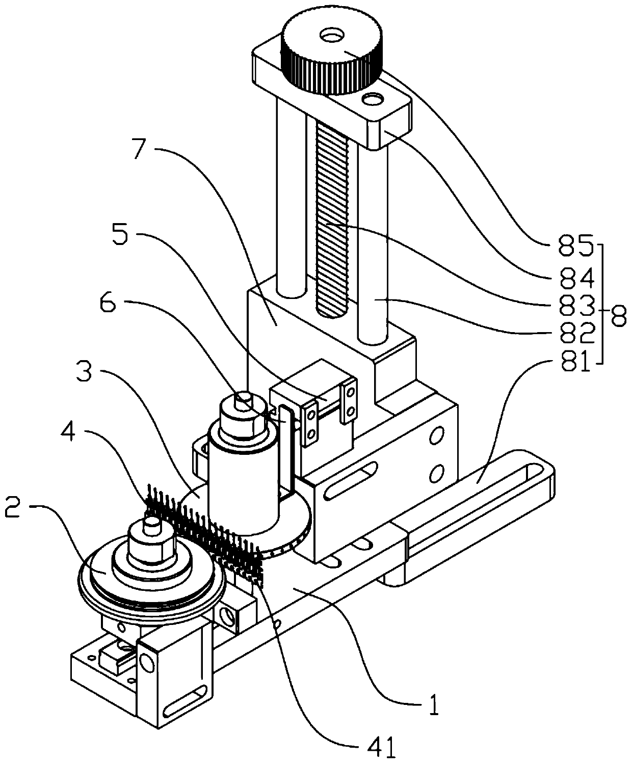
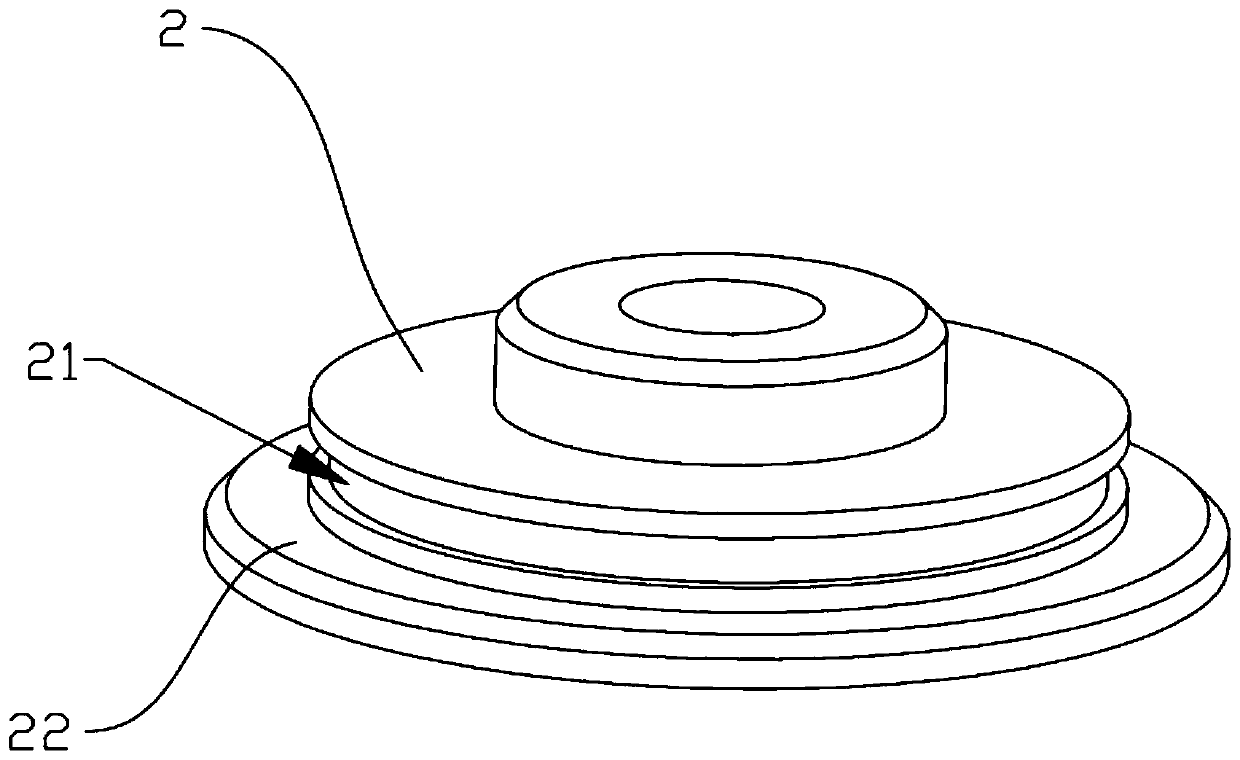
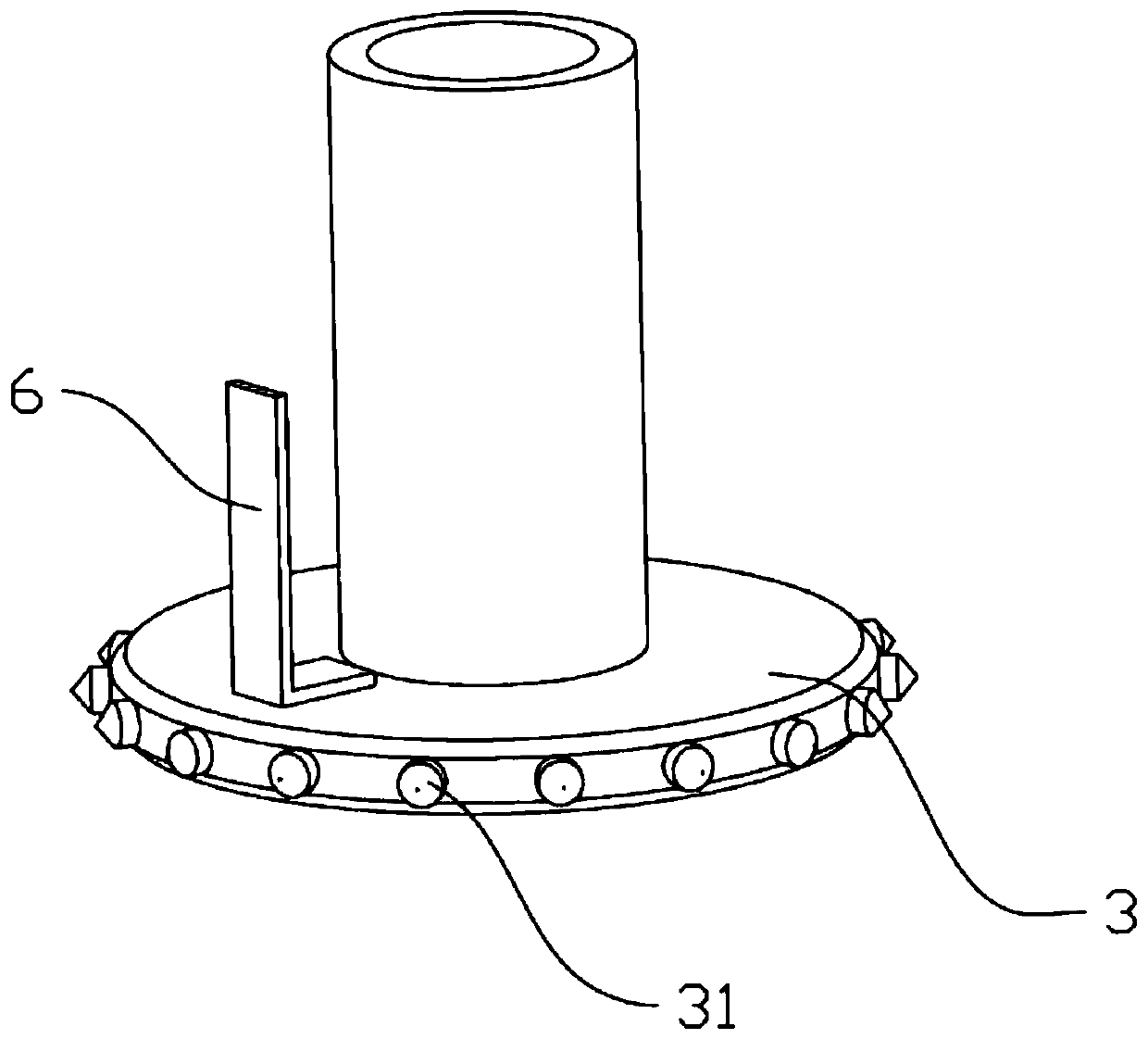
[0036] Such as figure 1 As shown, a counter fixture used on a high-speed electroplating production line includes a fixed base plate, and a clamping wheel and a counting guide wheel are rotated on the fixed base plate, and the clamping wheel and the counting guide wheel are described Positioning teeth are arranged on the circumference of the counting guide wheel, and a belt-shaped material is arranged between the clamping wheel and the counting guide wheel, and positioning holes corresponding to the positioning teeth are provided on the belt-shaped material. An optical fiber sensor is also arranged on the bottom plate, and a baffle plate passing through the optical fiber sensor at intervals is arranged on the counting guide wheel, and the baffle plate extends parallel to the axis of the counting guide wheel and is eccentrically arranged on the counting guide w...


PUM


Abstract

The invention discloses a counter jig for a high-speed electroplating production line. The counter jig comprises a fixed bottom plate, a material clamping wheel and a counting guide wheel are rotationally arranged on the fixed bottom plate; positioning teeth are arranged on the peripheral sides of the clamping wheel and the counting guide wheel; a strip-shaped material is arranged between the material clamping wheel and the counting guide wheel; positioning holes corresponding to the positioning teeth are formed in the strip-shaped materials, an optical fiber sensor is further arranged on thefixed bottom plate, and shielding plates passing through the optical fiber sensor at intervals are arranged on the counting guide wheel, extend in the direction parallel to the axis of the counting guide wheel and are eccentrically arranged on the counting guide wheel. Positioning teeth are arranged on the counting guide wheel, so that the positioning holes correspondingly pass through the positioning teeth; after the counting guide wheel rotates by a circle, the optical fiber sensor can indirectly obtain the specific number of the counting guide wheel positioning holes by recording the rotation turns of the counting guide wheel, the counting guide wheel reduces the high-frequency counting speed in a multiplied mode, and the manufacturing cost and the maintenance cost of equipment are greatly reduced on the premise that the counting precision is guaranteed.

Description

technical field [0001] The invention relates to a counting device of an electroplating production line, in particular to a counter jig used in a high-speed electroplating production line. Background technique [0002] Electroplating (Flectroplating) is the process of plating a thin layer of other metals or alloys on the surface of certain metals using the principle of electrolysis. It is a process of using electrolysis to attach a layer of metal film to the surface of metal or other material parts to prevent Metal oxidation (such as rust), improve wear resistance, electrical conductivity, reflective properties, corrosion resistance (copper sulfate, etc.) and enhance the appearance. [0003] Shells, terminals, and plates are produced as strip-shaped materials during electroplating for continuous production, and strip-shaped materials are usually transported by traction in order to facilitate continuous electroplating during electroplating. In the continuous production process...

Claims


Application Information

Patent Timeline
IPC IPC(8): G06M1/08G06M1/10
CPCG06M1/083G06M1/101
Inventor 张文标
Owner KUNSHAN SOKAY AUTOMATION TECH CO LTD
Learn More