
Optical module

An optical module and optical chip technology, applied in the field of optical modules, can solve problems such as poor heat dissipation effect, achieve good heat dissipation effect, and improve the effect of heat conduction area

Active Publication Date: 2020-04-24
HISENSE BROADBAND MULTIMEDIA TECH
View PDF9 Cites 7 Cited by
  • Summary
  • Abstract
  • Description
  • Claims
  • Application Information

AI Technical Summary

Problems solved by technology

[0004] The present invention provides an optical module to solve the problem of poor heat dissipation effect of the existing heat dissipation method for high energy density optical modules

Method used


Image

  • Optical module
  • Optical module
  • Optical module

Examples


Embodiment Construction

[0047] The following will clearly and completely describe the technical solutions in the embodiments of the present invention with reference to the accompanying drawings in the embodiments of the present invention. Obviously, the described embodiments are only some, not all, embodiments of the present invention. Based on the embodiments of the present invention, all other embodiments obtained by persons of ordinary skill in the art without creative efforts fall within the protection scope of the present invention.

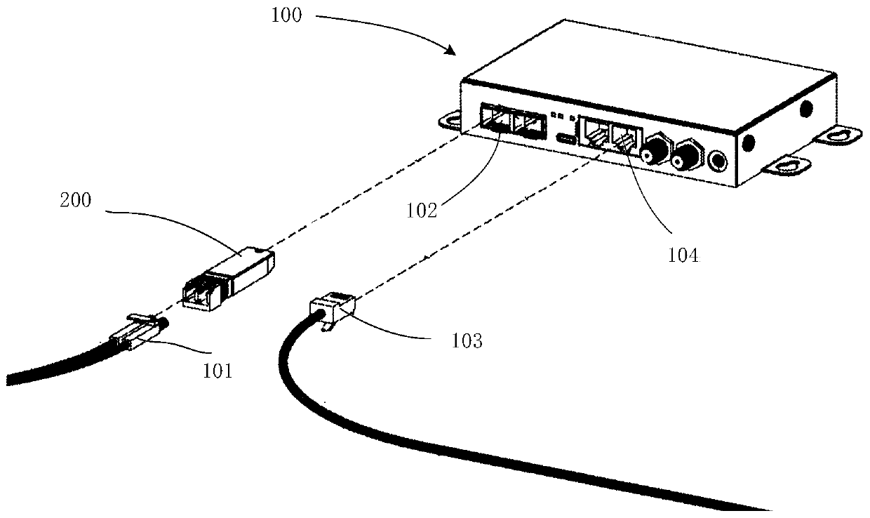
[0048] One of the core links of optical fiber communication is the mutual conversion of optical and electrical signals. Optical fiber communication uses optical signals carrying information to be transmitted in information transmission equipment such as optical fibers / optical waveguides, and the passive transmission characteristics of light in optical fibers / optical waveguides can be used to achieve low-cost, low-loss information transmission; and information proces...


PUM


Abstract

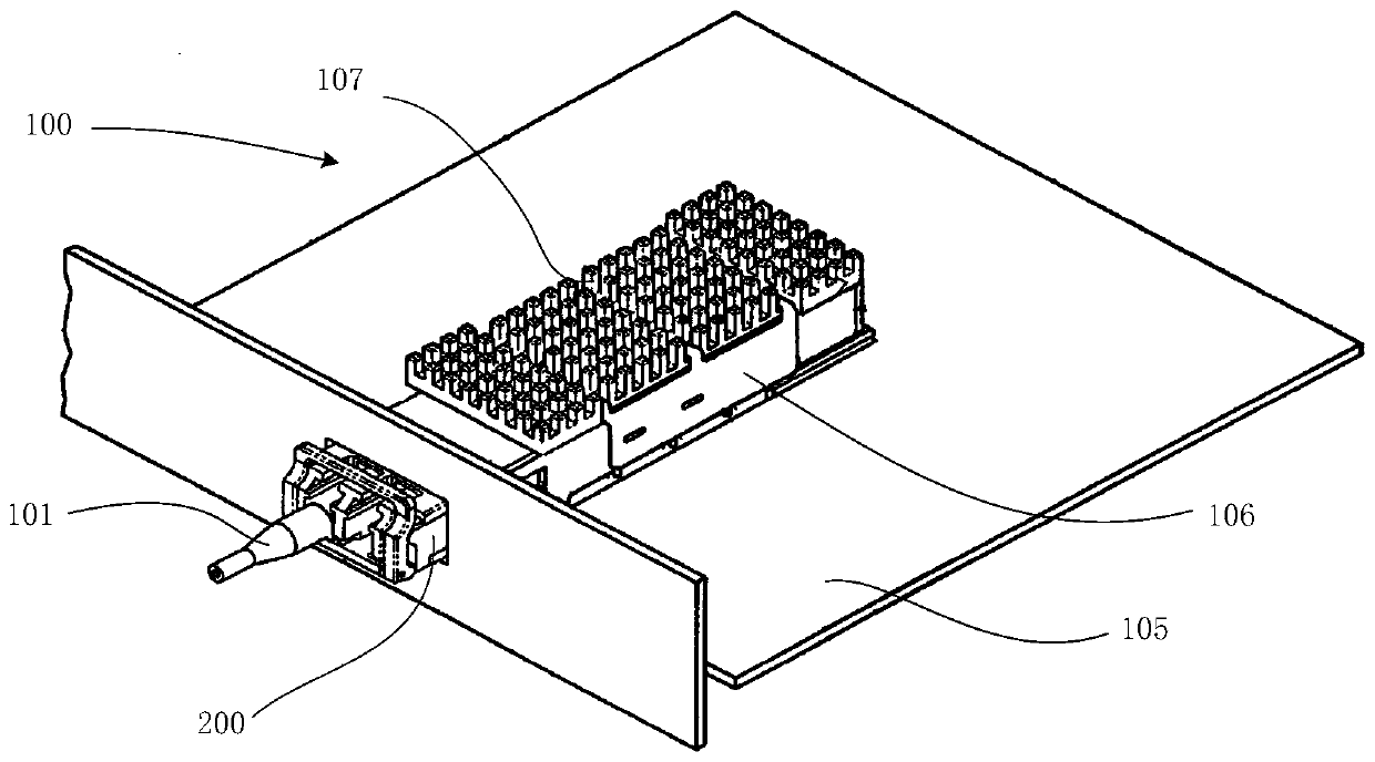
The invention discloses an optical module. A circuit board is provided with a first heat dissipation piece, an optical chip is attached to one end of the first heat dissipation piece, the other end ofthe first heat dissipation piece extends out of a lens assembly, the lens assembly covers the optical chip, a third heat dissipation piece and a through hole are arranged in the circuit board, and the first heat dissipation piece and the third heat dissipation piece are in heat conduction connection through the through hole. A second heat dissipation piece is arranged at the other end of the first heat dissipation piece and provided with a heat conduction piece, and the heat conduction piece is in heat conduction connection with an upper shell. The first heat dissipation piece conducts heat generated by the optical chip to the third heat dissipation piece, the third heat dissipation piece diffuses the heat and then conducts the heat to the first heat dissipation piece through the throughhole, and the first heat dissipation piece conducts the total heat to the second heat dissipation piece, and then the total heat is conducted to the upper shell through the heat conduction piece. Visibly, according to the optical module provided by the invention, the heat generated by the optical chip is diffused out of the coverage area of the lens assembly by utilizing the first heat dissipationpiece and the third heat dissipation piece, and then heat dissipation is realized by the second heat dissipation piece, the heat conduction piece and the upper shell, so that the heat dissipation effect is better.

Description

technical field [0001] The invention relates to the technical field of optical fiber communication, in particular to an optical module. Background technique [0002] With the advent of the 5G era, in order to achieve the requirements of 5G large bandwidth capacity, low latency, and network slicing, it is necessary to increase the transmission rate of optical communication. In order to increase the transmission rate of optical communication, 400G optical modules are used in this field to realize the transmission and reception of light of different wavelengths. [0003] The 400G optical module includes a printed circuit board (Printed Circuit board, referred to as: PCB), a laser set on the printed circuit board, a detector, and a driver chip for driving the laser and the detector. on the corresponding pad. Each device will generate heat during operation. If the heat cannot be dissipated quickly, the ambient temperature will continue to rise and affect the performance of the ...

Claims


Application Information

Patent Timeline
Patent Type & Authority Applications(China)
IPC IPC(8): G02B6/42
CPCG02B6/4268G02B6/4269G02B6/428
Inventor 姚建伟董本正徐发部于冬梅刘飞罗从文
Owner HISENSE BROADBAND MULTIMEDIA TECH
Learn More