Tooth engagement adjustment method and adjustment system for eccentric bushing type gearbox of heavy multi-stage vertical shaft

An adjustment system and adjustment method technology, applied to belts/chains/gears, transmission parts, mechanical equipment, etc., can solve problems such as heavy workload, disassembly, adjustment, assembly difficulty, abnormal vibration, etc., to reduce adjustment and The effect of detection work, shortening of tooth meshing adjustment time, and simple and ingenious structure design

Pending Publication Date: 2020-04-24
西马克工程(中国)有限公司
View PDF0 Cites 1 Cited by
  • Summary
  • Abstract
  • Description
  • Claims
  • Application Information

AI Technical Summary

Problems solved by technology

[0002] When the gear box is assembled, the contact position, contact area and meshing clearance of the teeth must be adjusted to meet the design requirements. If the design requirements are not met, the oil film is not easy to form between the tooth surfaces, and noise and abnormal vibration will be generated during work. Accidents such as tooth surface wear and even tooth breakage
[0003] The tooth meshing adjustment of the gearbox is a cumbersome work, which often requires repeated adjustments, and the workload is very heavy, especially for some heavy-duty multi-stage vertical shaft eccentric sleeve gearboxes, due to the large size and heavy weight of the gear shaft, It is very difficult to disassemble, adjust and assemble during the adjustment process, and it is not easy to adjust once

Method used


Image

  • Tooth engagement adjustment method and adjustment system for eccentric bushing type gearbox of heavy multi-stage vertical shaft
  • Tooth engagement adjustment method and adjustment system for eccentric bushing type gearbox of heavy multi-stage vertical shaft
  • Tooth engagement adjustment method and adjustment system for eccentric bushing type gearbox of heavy multi-stage vertical shaft

Examples


Embodiment Construction

[0037] The present invention will be described below according to the embodiments shown in the accompanying drawings. It can be thought that embodiment disclosed this time is an illustration in every point, and is not restrictive. The scope of the present invention is not limited by the description of the following embodiments but only by the scope of the claims, and includes the same meaning as the scope of the claims and all modifications within the scope of the claims.

[0038] The following describes the tooth engagement adjustment method and the structure of the adjustment system of the heavy-duty multi-stage vertical shaft eccentric sleeve type gearbox of the present invention in conjunction with specific embodiments.

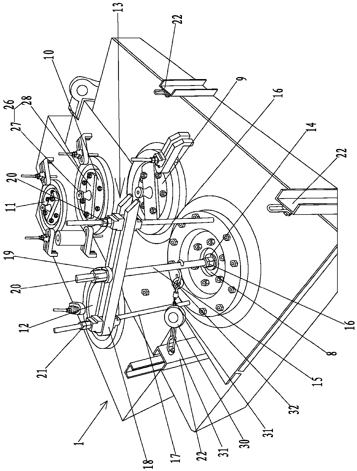
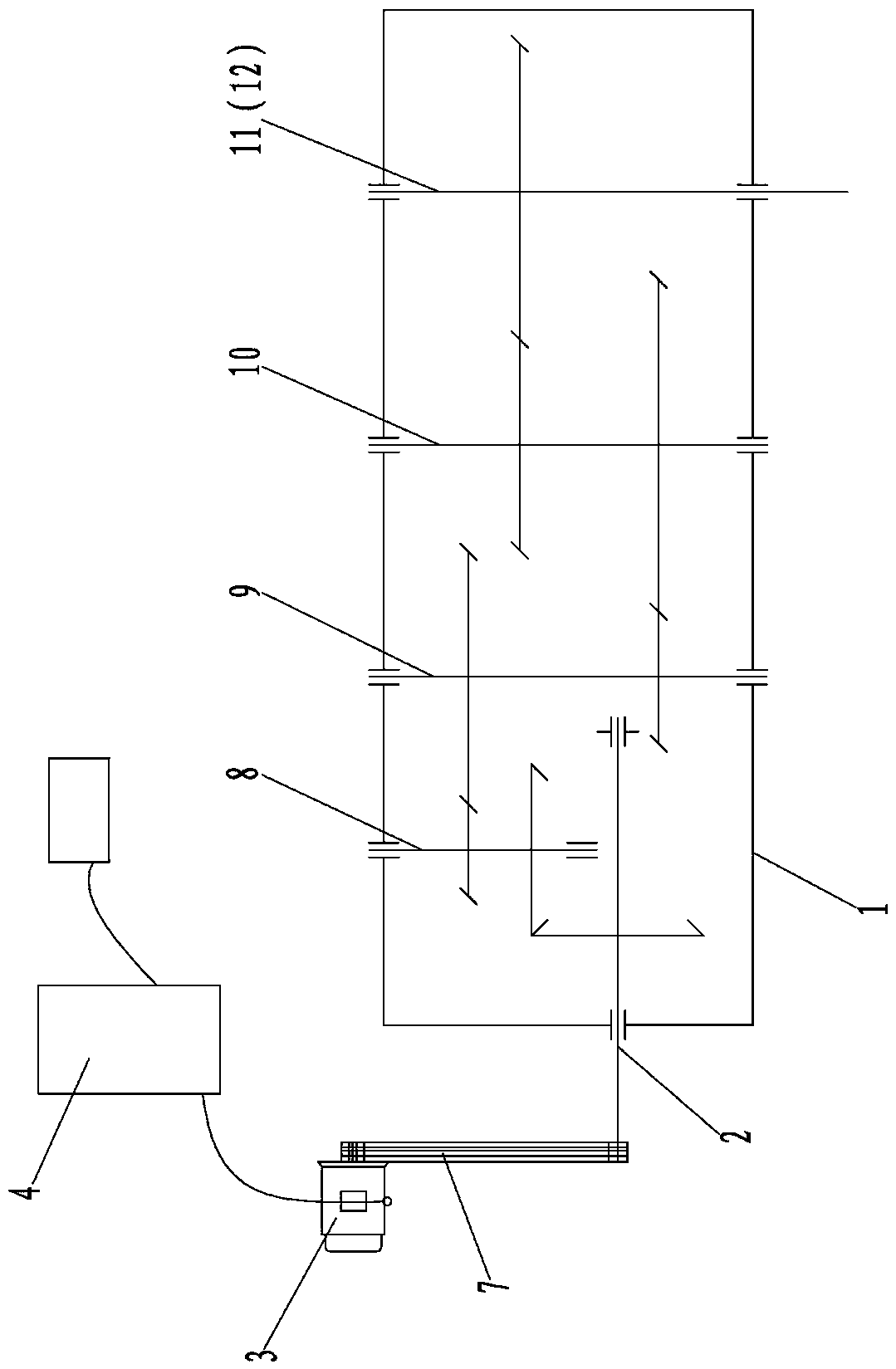
[0039] Such as figure 1 Shown is a three-dimensional structural schematic diagram of the heavy-duty multi-stage vertical shaft eccentric sleeve gear box gear mesh adjustment system of the present invention, which includes:

[0040] Drive unit: used to p...


PUM


Abstract

The invention relates to a tooth engagement adjustment method and adjustment system for an eccentric bushing type gearbox of a heavy multi-stage vertical shaft. The adjustment method comprises the following steps of adjusting the gearbox to a preset height by a box body positioning assembly; adjusting the axial position of each to-be-adjusted gear to a preset position through each axial positioning device; starting a driving device on an input shaft to apply a radial load force to the to-be-adjusted gear shaft through a load device connected to the to-be-adjusted gear shaft adjacent to the input shaft; stopping the driving device working for a preset time to detect the tooth engaging condition of each to-be-adjusted gear; and when the tooth generation is not qualified, adjusting an eccentric bushing on each to-be-adjusted gear and repeating the previous step; when the tooth engagement is qualified, adjusting the tooth engaging condition of each adjacent to-be-adjusted gear successivelyaccording to the steps, and when the tooth engagement is not qualified, repeating the previous step till adjusting all the to-be-adjusted gears. The method can improve the adjustment accuracy, optimize an operating process and reduce the adjustment workload properly, and the adjustment system is simple and skillful in structural design.

Description

technical field [0001] The invention relates to the technical field of tooth mesh adjustment of a heavy-duty multistage gearbox, in particular to a tooth mesh adjustment method and an adjustment system for a gearbox with a heavy multistage vertical gear shaft and an eccentric sleeve for adjustment. Background technique [0002] When the gear box is assembled, the contact position, contact area and meshing clearance of the teeth must be adjusted to meet the design requirements. If the design requirements are not met, the oil film is not easy to form between the tooth surfaces, and noise and abnormal vibration will be generated during work. Accidents such as tooth surface wear, or even tooth breakage. [0003] The tooth meshing adjustment of the gearbox is a cumbersome work, which often requires repeated adjustments, and the workload is very heavy, especially for some heavy-duty multi-stage vertical shaft eccentric sleeve gearboxes, due to the large size and heavy weight of th...

Claims


Application Information

Patent Timeline
Patent Type & Authority Applications(China)
IPC IPC(8): F16H57/023F16H57/12
CPCF16H57/023F16H57/12F16H2057/125
Inventor 赵海涛王强石传如陈毅彬吕建新
Owner 西马克工程(中国)有限公司
Why Eureka
Try Eureka