
Pile pressing machine automatic position searching method and system

A pile driver, automatic technology, applied in the direction of satellite radio beacon positioning system, radio wave measurement system, sheet pile wall, etc., can solve the problems of long time consumption, complicated process, and inability to obtain the direction and position of pile driver in real time, and achieve The effect of improving drilling accuracy and reducing personnel input

Inactive Publication Date: 2020-04-24
福建建中建设科技有限责任公司
View PDF10 Cites 4 Cited by
  • Summary
  • Abstract
  • Description
  • Claims
  • Application Information

AI Technical Summary

Problems solved by technology

In the process of urban construction, pile drivers have been widely used on a large scale. With the development of pile drivers and the enhancement of environmental protection awareness, the static pile method has been further promoted. However, in the construction process of pile drivers, the equipment The walking of the pile and the precise positioning of the hole require the use of a total station for measurement, stakeout and other operations. The direction and position of the pile driver cannot be obtained in real time. The process is complex, time-consuming and requires the cooperation of multiple people

Method used


Image

  • Pile pressing machine automatic position searching method and system
  • Pile pressing machine automatic position searching method and system
  • Pile pressing machine automatic position searching method and system

Examples


Embodiment 1

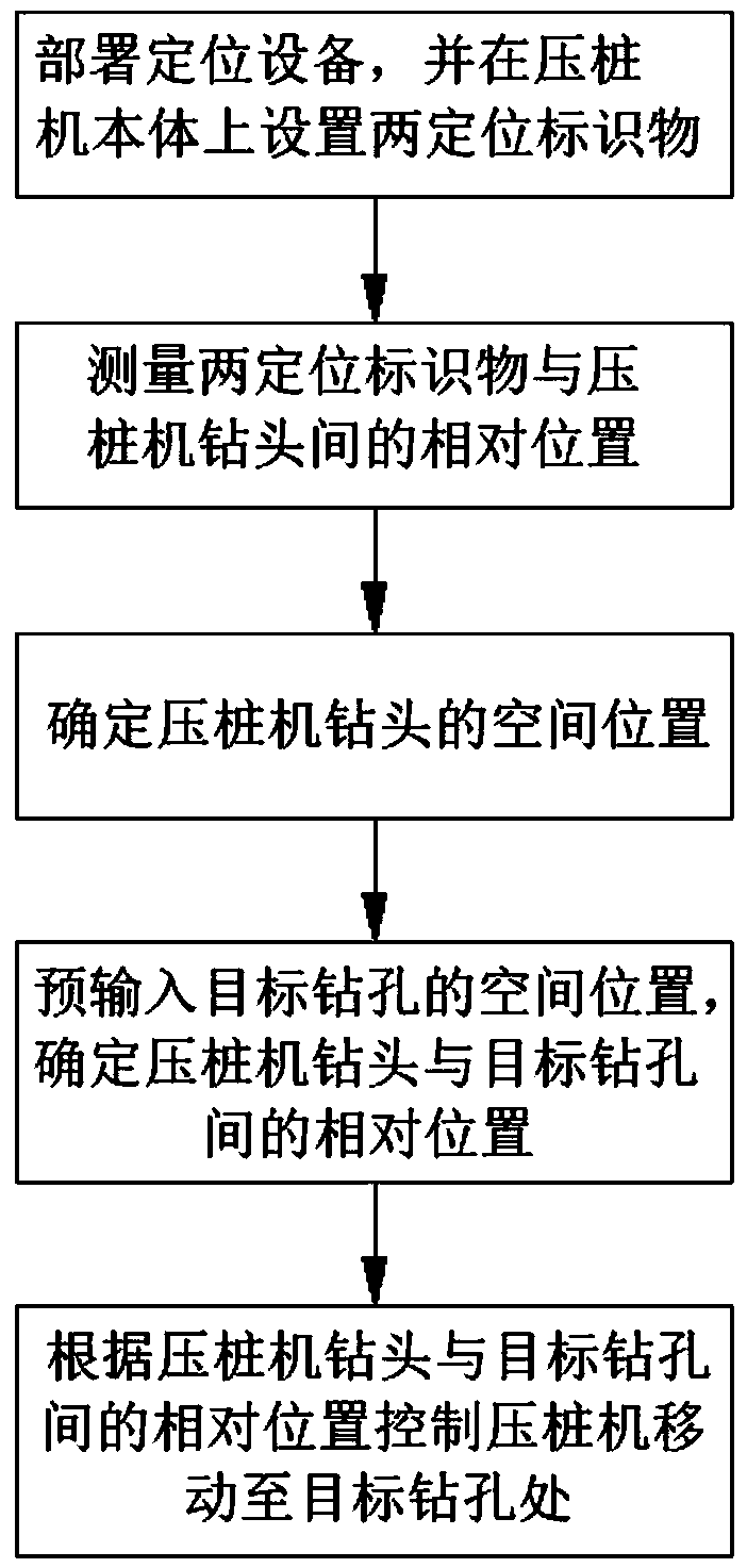
[0037] A method for automatically finding the position of a pile driver, comprising the following steps:

[0038] Deploy positioning equipment and set two positioning markers on the pile driver body;

[0039] Measure the relative position between the two positioning markers and the drill bit of the pile driver respectively;

[0040] Obtain the spatial positions of the two positioning markers by the positioning device, and determine the spatial position of the pile driver drill according to the spatial positions of the two positioning markers and the relative position between the two positioning markers and the pile driver drill bit;

[0041] Pre-input the spatial position of at least one pile hole that needs to be pressed, select a pile hole as the target pile hole, and determine the relationship between the pile driver drill bit and the target pile hole through the spatial position of the target pile hole and the spatial position of the pile driver drill bit. The relative po...

Embodiment 2

[0045] In this embodiment, on the basis of Embodiment 1, further, the positioning device is a satellite positioning system or a high-precision positioning system based on satellite positioning, such as GPS satellite positioning system, Beidou satellite positioning system, and the like. The positioning marker is a GNSS antenna.

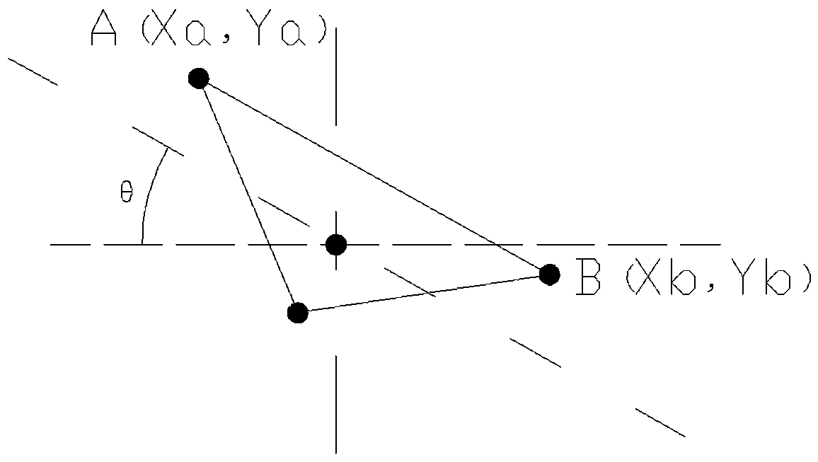
[0046] Further, see Figure 2 to Figure 4 , also includes a correcting step for correcting the spatial positions of the two positioning markers, specifically as follows:

[0047] The pile driver body is also provided with a six-axis gyroscope, and the six-axis gyroscope obtains the inclination angle between the pile driver body and the horizontal plane, such as figure 2 As shown, the tilt angle obtained by the six-axis gyroscope is θ;

[0048] see Figure 4 , to establish a plane Cartesian coordinate system horizontal to the ground; D, E, and F are the coordinates of the pre-input target borehole.

[0049] Acquiring the positioning coordinates A (...

Embodiment 3

[0054] A system for automatic positioning of a pile driver, comprising:

[0055] A positioning module, the positioning module includes a positioning device and two positioning markers arranged on the pile driver body;

[0056] The measurement module is used to measure the relative position between the two positioning markers and the drill bit of the pile driver;

[0057]A calculation module, configured to calculate the spatial position of the pile driver bit according to the spatial position of the two positioning markers and the relative position between the two positioning markers and the pile driver bit;

[0058] The input module is used to input the spatial position of at least one pile hole that needs to be pressed;

[0059] The control module is used to issue control commands to the electronic control system of the pile driver to control the movement of the pile driver.

[0060] This embodiment determines the spatial position of the center point of the drill bit by set...


PUM


Abstract

The invention relates to a pile pressing machine automatic position searching method and system. The automatic position searching method comprises the following steps that positioning equipment is arranged, and two positioning markers are set on a pile pressing machine body; the relative positions between the two positioning markers and a pile pressing machine drill bit are measured; the positioning equipment is used for obtaining the space positions of the two positioning markers, and the space position of the pile pressing machine drill bit is determined according to the space positions of the two positioning markers and the relative positions between the two positioning markers and the pile pressing machine drill bit; the pile hole space position is pre-input, one pile hole is selectedas a target pile hole, and the relative position between the pile pressing machine drill bit and the target pile hole is determined according to the space position of the target pile hole and the space position of the pile pressing machine drill bit; and according to the relative position of the pile pressing machine drill bit and the target pile hole, an instruction is issued to an electric control system of a pile pressing machine, the pile pressing machine is controlled to move, and the space position of the pile pressing machine drill bit coincides with the space position of the target pile hole.

Description

technical field [0001] The invention relates to an automatic positioning method and system for a pile driver, belonging to the technical field of pile drivers. Background technique [0002] A pile driver is a pile machine that uses static pressure to press piles into the ground. It is used for soft soil laminated piles, such as pile construction in underground railways, seaports, bridges, reservoir power stations, offshore oil production platforms and national defense projects. In the process of urban construction, pile drivers have been widely used on a large scale. With the development of pile drivers and the enhancement of environmental protection awareness, the static pile method has been further promoted. However, in the construction process of pile drivers, the equipment The walking of the pile and the precise positioning of the hole require the use of a total station for measurement, stakeout and other operations. The direction and position of the pile driver cannot ...

Claims


Application Information

Patent Timeline
Patent Type & Authority Applications(China)
IPC IPC(8): E02D13/04E02D7/20G01S19/42G01C9/00
CPCE02D13/04E02D7/20G01S19/42G01C9/00
Inventor 项箐唐文谢忠辛正勇陈永智陈敏捷王杰成魏珊珊尹立炜檀烽沈程佩汤晓妃张新新
Owner 福建建中建设科技有限责任公司
Learn More