
Pressure machine capable of driving balance mechanism

A technology of balance mechanism and press, which is applied in the field of press components, can solve the problems of poor balance, difficult processing, troublesome assembly, etc., and achieve the effect of meeting the requirements of use, good dynamic balancing effect and simple structure

Pending Publication Date: 2020-04-24
JDM JINGDA MASCH (NINGBO) CO LTD
View PDF0 Cites 0 Cited by
  • Summary
  • Abstract
  • Description
  • Claims
  • Application Information

AI Technical Summary

Problems solved by technology

Among the dynamic balance mechanisms used in existing presses, the most ideal is the anti-slider mechanism, which can basically balance the inertial force generated during the operation of the press. However, due to its complex structure, difficult processing, and troublesome assembly, it must be limited its scope of application
[0003] In addition, in the existing presses, the slider is usually driven by two points of force, and its balance is also poor

Method used


Image

  • Pressure machine capable of driving balance mechanism
  • Pressure machine capable of driving balance mechanism
  • Pressure machine capable of driving balance mechanism

Examples


Embodiment Construction

[0012] The present invention will be further described in detail below in conjunction with the accompanying drawings and embodiments.

[0013] For the convenience of description, according to the direction of the accompanying drawings, the A-A centerline and B-B centerline in the figure are determined to be the front and rear centerlines and left and right centerlines of the press respectively, but the determination of the A-A centerline and B-B centerline does not constitute protection for the present invention Limitations on Content and Scope.

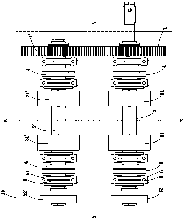
[0014] Such as Figure 1-3 As shown, a press includes a base 6, a slider 7, a column 8, an upper beam 10 and a dynamic balance mechanism.

[0015] There are four columns 8, which are respectively installed on the four corners of the base 6, and the upper beam 10 is supported by the columns 8 to form the frame of the press.

[0016] The first transmission shaft 2 and the second transmission shaft 2' are rollingly supported by the up...


PUM


Abstract

The invention discloses a pressure machine capable of driving a balance mechanism. The pressure machine comprises sliding blocks, upper beams, dynamic balance mechanisms; one ends of first transmission shafts of the dynamic balance mechanisms are connected with driving gears, one ends of second transmission shafts are connected with driven gears, the driving gears mesh with the driven gears, the first transmission shafts and the second transmission shafts are symmetrically arranged according to the horizontal center of the sliding blocks, the vertical center of each sliding block is taken as the center, force application bearings are symmetrically arranged on the two sides of the first transmission shafts and the second transmission shafts respectively, the force application bearings are eccentrically arranged, the two sides of each force application bearing are symmetrically provided with support bearings, and the support bearings support the first transmission shafts and the second transmission shafts. First balance blocks take the vertical center of the sliding blocks as the center, the two sides of the first balance blocks are arranged on the first transmission shafts and the second transmission shafts correspondingly, second balance blocks are arranged on the other sides of the first transmission shafts and the second transmission shafts; second balance blocks take the horizontal center of the sliding blocks as the center and are symmetrically arranged, third balance blocks are arranged on the two sides of the driving gears and driven gears as the symmetric center according to the gear thickness, and the first balance blocks, the second balance blocks and the third balance blocks are opposite to the eccentric direction of the force application bearings.

Description

technical field [0001] The invention relates to components of a press, in particular to a dynamic balance mechanism for eliminating the inertia force of the press. Background technique [0002] With the continuous improvement of production enterprises' requirements for the speed of presses, high-speed presses have been widely used, but the press will inevitably generate inertial force when running at high speed. The higher the speed, the greater the inertial force. A well-balanced inertial force will make the dynamic performance of the bottom dead center of the press slider very poor, which will affect the precision of the press and the life of the mold at the slightest, and may damage the press and the mold and make it unusable. Therefore, it is very necessary to balance the inertial force of the high-speed press. Among the dynamic balance mechanisms used in existing presses, the most ideal is the anti-slider mechanism, which can basically balance the inertial force genera...

Claims


Application Information

Patent Timeline
IPC IPC(8): B30B15/00
CPCB30B15/0064
Inventor 陈泉剑
Owner JDM JINGDA MASCH (NINGBO) CO LTD
Learn More