
Transmission machine and fan

A transmission machine and fan technology, applied in the direction of machines/engines, liquid fuel engines, electromechanical devices, etc., can solve the problems of fan system efficiency loss and other issues

Pending Publication Date: 2020-04-21
河北汉诺威环保机械有限公司
View PDF0 Cites 0 Cited by
  • Summary
  • Abstract
  • Description
  • Claims
  • Application Information

AI Technical Summary

Problems solved by technology

At the same time, during this process, the bearings in the transmission system share the radial force and axial force of the impeller, but the motor and the impeller are connected through the transmission system, so the efficiency of the fan system will be lost, and the loss is at least 1%.

Method used


Image

  • Transmission machine and fan
  • Transmission machine and fan
  • Transmission machine and fan

Examples


Embodiment Construction

[0025] The present invention will be described in detail below with reference to the accompanying drawings and examples. Each example is provided by way of explanation of the invention, not limitation of the invention. In fact, those skilled in the art will recognize that modifications and variations can be made in the present invention without departing from the scope or spirit of the invention. For example, features illustrated or described as part of one embodiment can be used on another embodiment to yield a still further embodiment. Therefore, it is intended that the present invention includes such modifications and variations as come within the scope of the appended claims and their equivalents.

[0026] In the description of the present invention, the terms "longitudinal", "transverse", "upper", "lower", "front", "rear", "left", "right", "vertical", "horizontal", " The orientations or positional relationships indicated by "top", "bottom", etc. are based on the orienta...


PUM


Abstract

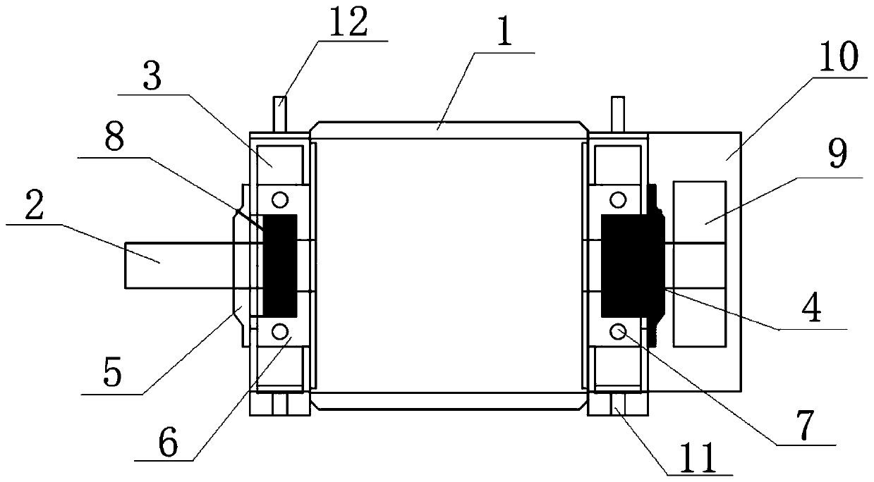
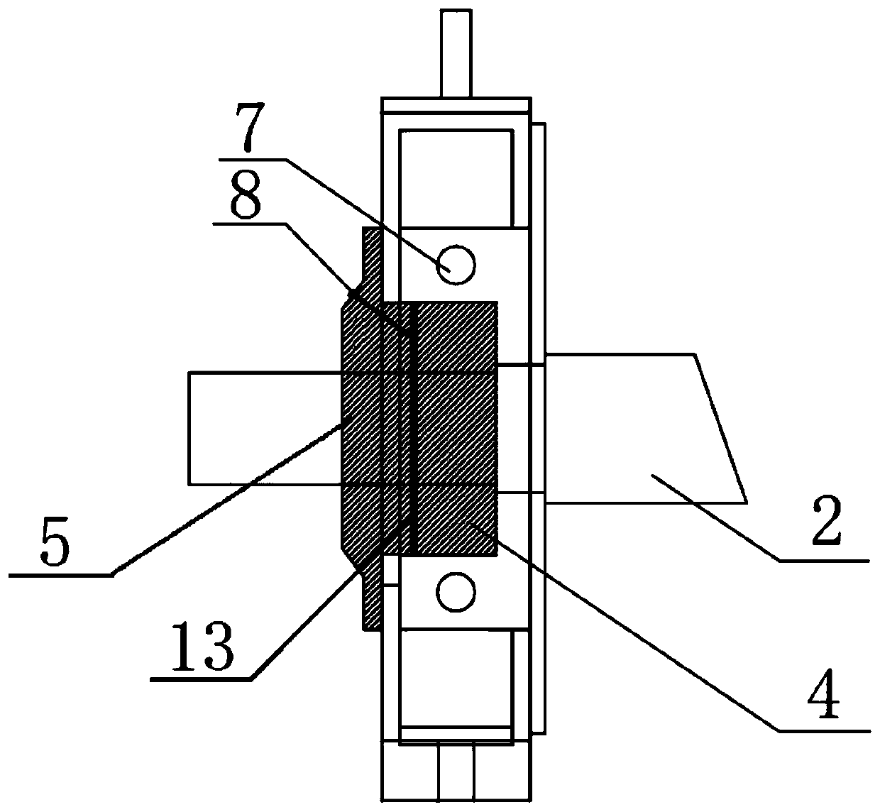
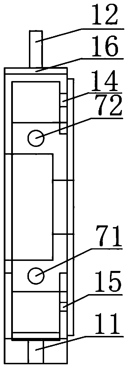
The invention provides a transmission machine and a fan. The transmission machine comprises a shell and a driving device, a transmission system and supporting systems which are installed on the shell.The driving device is arranged in the shell and used for providing driving force for the transmission machine; the transmission system and the driving device share the main shaft, and the transmission system is used for transmitting torque of the main shaft to an external mechanism; the supporting systems are arranged at the two ends of the main shaft and used for supporting the transmission machine. The structure of the transmission machine is designed, the transmission machine is enabled to have the transmission shaft, namely the main shaft, with the enough length, power generated by the driving device can be stably transmitted, the impeller of the transmission machine is directly connected with the main shaft of the driving device, the link of connecting through a coupler in the process is omitted and energy loss is effectively avoided. A water circulation system is arranged, timely and effective heat dissipation of the transmission machine is achieved, and the service life of thetransmission machine is further prolonged. The fan utilizes the transmission machine and has the advantages of being high in transmission efficiency and long in service life.

Description

technical field [0001] The invention relates to the technical field of mechanical transmission, in particular to a transmission machine and a fan. Background technique [0002] The working principle of the fan in the prior art is generally: the motor generates mechanical kinetic energy after being energized, and transmits it to the main shaft of the transmission system through the coupling. Since the main shaft is connected with the impeller, the rotation of the main shaft drives the impeller to rotate at the same time, thereby generating the mechanical energy of the fan. , the impeller converts the mechanical energy of the fan into the kinetic energy of the air. At the same time, during this process, the bearings in the transmission system share the radial force and axial force of the impeller, but the motor and the impeller are connected through the transmission system, so the efficiency of the fan system will be lost, and the loss is at least 1%. Therefore, it is very ne...

Claims


Application Information

Patent Timeline
IPC IPC(8): H02K7/14H02K5/16H02K9/19F04D25/08F04D29/58
CPCF04D25/08F04D29/582H02K5/161H02K7/14H02K9/19
Inventor 王学海
Owner 河北汉诺威环保机械有限公司
Learn More