
Anti-overcurrent fine adjustment slide rheostat

A sliding rheostat and overcurrent technology, applied in the direction of sliding contact resistors, adjustable resistors, resistors, etc., can solve the problems of damaged rheostats, inability to finely adjust the resistance, and easy heating

Inactive Publication Date: 2020-04-21
HUBEI UNIV OF TECH
View PDF1 Cites 1 Cited by
  • Summary
  • Abstract
  • Description
  • Claims
  • Application Information

AI Technical Summary

Problems solved by technology

[0004] Based on the technical problems that the existing sliding rheostats are prone to heat during operation and damage the rheostats, and at the same time the resistance cannot be finely adjusted, the present invention proposes a fine-tuning sliding rheostat for preventing overcurrent

Method used


Image

  • Anti-overcurrent fine adjustment slide rheostat
  • Anti-overcurrent fine adjustment slide rheostat
  • Anti-overcurrent fine adjustment slide rheostat

Examples


Embodiment 1

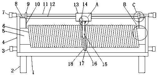
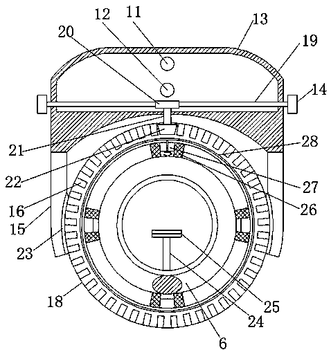
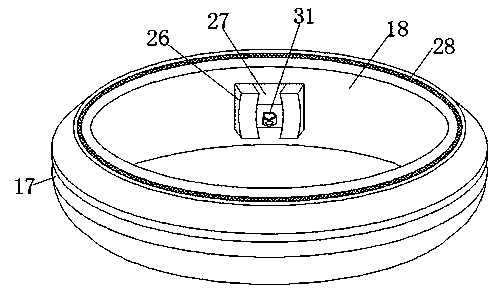
[0030] refer to Figure 1-6 , an anti-overcurrent fine-tuning sliding rheostat, comprising a bottom plate 1, fixed plates 4 are welded on both sides of the top of the bottom plate 1, fixed tubes 5 are welded between the fixed plates 4, fixed columns 24 are welded inside the fixed tubes 5, fixed The top of the column 24 is welded with a bimetallic strip 25, the outside of the fixed tube 5 is sheathed with a resistance wire 6, a second conductor 11 and a third conductor 12 are arranged between the two fixed plates 4, and both ends of the third conductor 12 are A first conductor 9 is rotatably connected, and the top of the fixed tube 5 is provided with two first through holes, and the fixed tube 5 is provided with a moving column 10 at the two first through holes, and the moving column 10 is located between the bimetal sheet 25 and the first through hole. Between one conductor 9, the middle part of the second conductor 11 and the third conductor 12 is provided with a moving body ...

Embodiment 2

[0043] refer to Figure 7 , an anti-overcurrent fine-tuning sliding rheostat. Compared with Embodiment 1, this embodiment increases the practicability of the device and prevents the rotating ring 18 and the resistance wire 6 from falling off when the moving body 13 slides. Both sides of the top of the bottom plate 1 are The limit block 32 is welded, the side of the limit block 32 close to each other is bonded with a rubber pad 33, when the rotating ring 18 moves to both sides, it will contact the rubber pad 33 for buffering, and stop the movement through the limit block 32 .

[0044] When changing the resistance value, moving the moving body 13 can drive the rotating ring 18 to move through the fixed rod 15, and the moving ring 18 drives the elastic sheet 31 to move, and the elastic sheet 31 contacts the different turns of the resistance wire 6, changing the resistance, and the current can pass through The first terminal 3 enters the resistance wire 6, and then enters the con...


PUM


Abstract

The invention belongs to the technical field of rheostats, and particularly relates to an anti-overcurrent fine adjustment slide rheostat. In view of the problems that an existing slide rheostat is easy to generate heat during working to result in damage of the rheostat, and that the resistance cannot be finely adjusted at the same time, the invention puts forward the following scheme: the slide rheostat comprises a bottom plate, fixing plates are welded to the two sides of the top end of the bottom plate, a fixing pipe is welded between the fixing plates, a fixing column is welded into the fixing pipe, a bimetallic strip is welded to the top end of the fixing column, the fixing pipe is externally sleeved with a resistance wire, and a second conductor and a third conductor are arranged between the two fixing plates. According to the invention, a worm gear drives a transmission shaft to rotate, a bevel gear is enabled to rotate and drive a rotating ring to rotate through a tooth groove,the rotating ring drives an elastic piece to rotate, the elastic piece slides on the resistance wire so as to achieve the purpose of the fine adjustment, the resistance wire generates heat to enablethe bimetallic strip to deform, a moving column rises and enables a first conductor to rotate through a push rod, the first conductor is separated from the second conductor, and the device is disconnected.

Description

technical field [0001] The invention relates to the technical field of rheostats, in particular to an anti-overcurrent fine-tuning sliding rheostat. Background technique [0002] The sliding rheostat is an electrical device that can change the resistance value. The existing sliding rheostat tends to generate heat during operation, especially when the current is over-current, the heating is more serious, and it is very likely to damage the rheostat. At the same time, when the existing sliding rheostat is adjusted, You can only increase or decrease the resistance of one turn of the resistance wire, and you cannot make fine adjustments to the resistance. [0003] After searching, the Chinese patent application number is CN201180020171.5, which discloses an overvoltage protection element with a housing, a connector for electrically connecting the overvoltage protection element to the current or signal line to be protected, Two varistors arranged in parallel and electrically con...

Claims


Application Information

Patent Timeline
Patent Type & Authority Applications(China)
IPC IPC(8): H01C10/30H01C10/34H01C10/38H01C1/00
CPCH01C1/00H01C10/301H01C10/34H01C10/38
Inventor 汪繁荣向堃彭禄方娜钟丹
Owner HUBEI UNIV OF TECH
Learn More