Conditional contact-bearing linear separation ring

A separation ring and conditional technology, which is applied in the aerospace field, can solve the problems of poor axial pressure bearing capacity of the separation ring, achieve the effect of suppressing local bending deformation and preventing buckling, instability and damage under axial pressure

Active Publication Date: 2020-04-21
DALIAN UNIV OF TECH
View PDF6 Cites 5 Cited by
  • Summary
  • Abstract
  • Description
  • Claims
  • Application Information

AI Technical Summary

Problems solved by technology

[0004] Aiming at the problem of poor axial pressure bearing capacity of the separation ring in the prior art, the present invention proposes a conditional contact bearing linear separation ring without changing the thickness of the separation plate and the charge amount of the pyrotechnic device. The contact bearing modules are added on both sides of the weakening groove of the separation plate, and the contact load is used to resist the additional bending moment, which changes the bearing mode of the line separation ring under axial pressure load, so that on the premise of ensuring the reliability of the horizontal line separation of the line separation ring, Effectively improve the axial bearing capacity of the structure

Method used


Image

  • Conditional contact-bearing linear separation ring
  • Conditional contact-bearing linear separation ring
  • Conditional contact-bearing linear separation ring

Examples


Embodiment Construction

[0024] In order to make the purpose, features and advantages of the present invention more obvious and understandable, the present invention will be further described below with reference to the accompanying drawings and in conjunction with specific embodiments, so that those skilled in the art can implement it with reference to the description. The scope of protection is not limited to this specific embodiment. Apparently, the embodiments described below are only some, not all, embodiments of the present invention. Based on the embodiments of the present invention, all other embodiments obtained by persons of ordinary skill in the art without making creative efforts belong to the protection scope of the present invention.

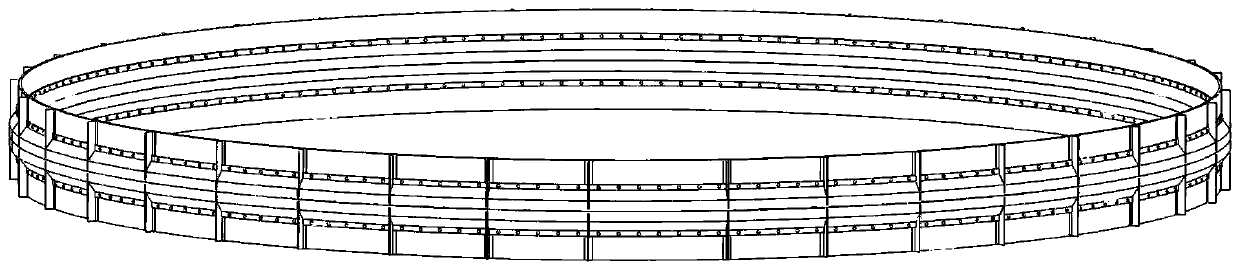
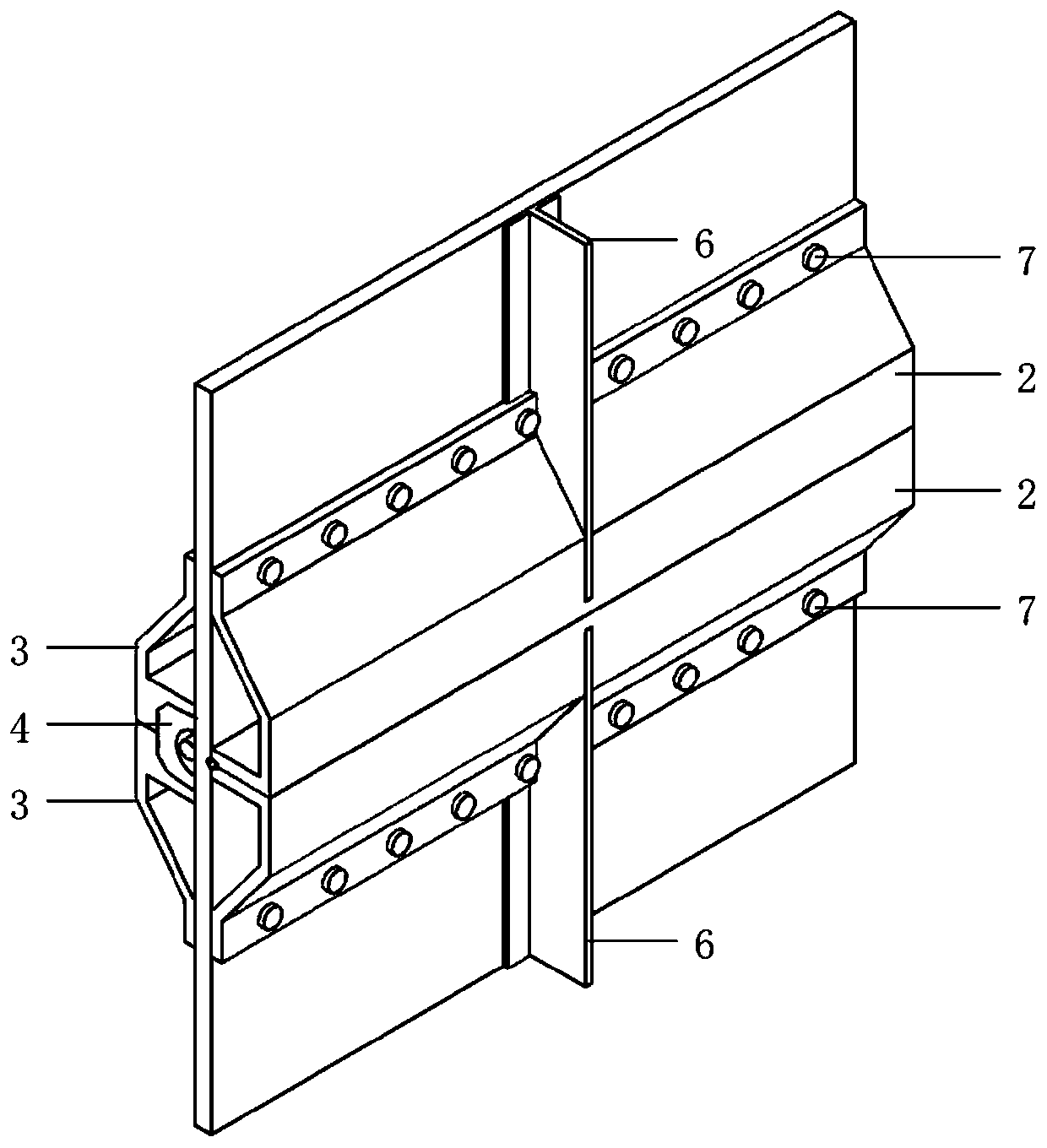
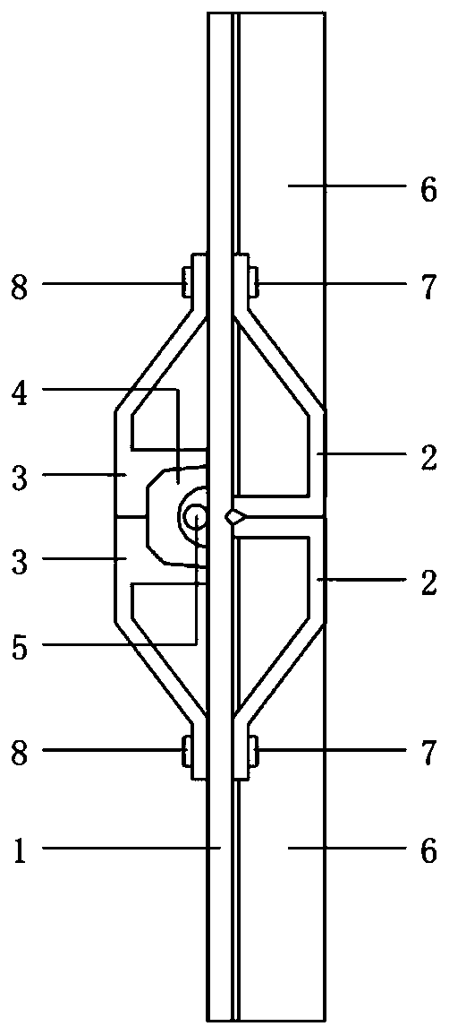
[0025] A conditional contact-bearing linear separation ring, the linear separation ring includes a separation plate 1, an outer contact bearing module 2, an inner contact bearing module 3, a rigid stopper 4, an energy-gathering cutting cable 5, and a skin ...


PUM


Abstract

The invention discloses a conditional contact-bearing linear separation ring, and belongs to the technical field of aerospace. The separation ring comprises a separation plate, inter contact bearing modules, external contact bearing modules, a rigid stop block, an energy-gathered cutting cable and skin stringers, wherein the separation plate, the inter and external contact bearing modules and theskin stringers are connected through bolts. An annular separation weakening groove is formed in the outer surface of the separation plate; the two external contact bearing modules are fixed to the outer surface of the separation plate and symmetrically installed on the two sides of the separation weakening groove; the two inner contact bearing modules are fixed to the inner surface of the separation plate and are symmetrically installed; the rigid stop block is mounted in a space formed by two stop block assembling grooves, and the energy-gathered cutting cable is installed in the rigid stop block and is aligned with the separation weakening groove; and the skin stringers are fixed on the outer surface of the separation plate. According to the separation ring, the contact bearing modules are additionally arranged on the two sides of the weakening groove of the separation plate, the bearing mode of the linear separation ring under the axial pressure load is changed, and the axial bearing capacity of the structure is effectively improved on the premise that the transverse line separation reliability of the linear separation ring is guaranteed.

Description

technical field [0001] The invention belongs to the field of aerospace technology, and relates to a conditional contact bearing wire type separation ring. Background technique [0002] For heavy-duty launch vehicles and missiles, wire-type separation devices, namely wire-type separation rings, are mostly used for the connection and separation of the interstage sections. In normal service environment, two adjacent stages of a rocket or missile are connected by a line separation ring, and the separation plate in it bears the axial tension or axial compression load. When the separation device is working, the pyrotechnic expansion tube or energy-gathering detonating cord will cut off the separation plate in the linear separation ring along the weakening groove to achieve the purpose of inter-stage separation. Because the separation plate has the active feature defect of the weakened groove, the axial bearing capacity of the separation plate is greatly reduced. Especially under...

Claims


Application Information

Patent Timeline
IPC IPC(8): F42B15/36
CPCF42B15/36
Inventor 石云峰郝鹏王博曾杜娟吴浩蒋亮亮刘长治
Owner DALIAN UNIV OF TECH
Why Eureka
Try Eureka