
Rotary self-water-absorption floor tile

A rotary, floor tile technology, applied in the directions of roads, pavement details, side ditch/curbstone, etc., can solve the problems of poor water absorption, easy to accumulate water on the surface of floor tiles, and pedestrians are prone to slip and fall. The effect of improving water absorption and increasing friction

Inactive Publication Date: 2020-04-21
燕燕
View PDF0 Cites 12 Cited by
  • Summary
  • Abstract
  • Description
  • Claims
  • Application Information

AI Technical Summary

Problems solved by technology

[0003] Since most of the floor tiles are fired from clay and have poor water absorption, water is prone to accumulate on the surface of the floor tiles in rainy weather. Once water accumulates on the surface of the floor tiles, pedestrians are prone to slip and fall, especially for the elderly or This is especially true for people with disabilities

Method used

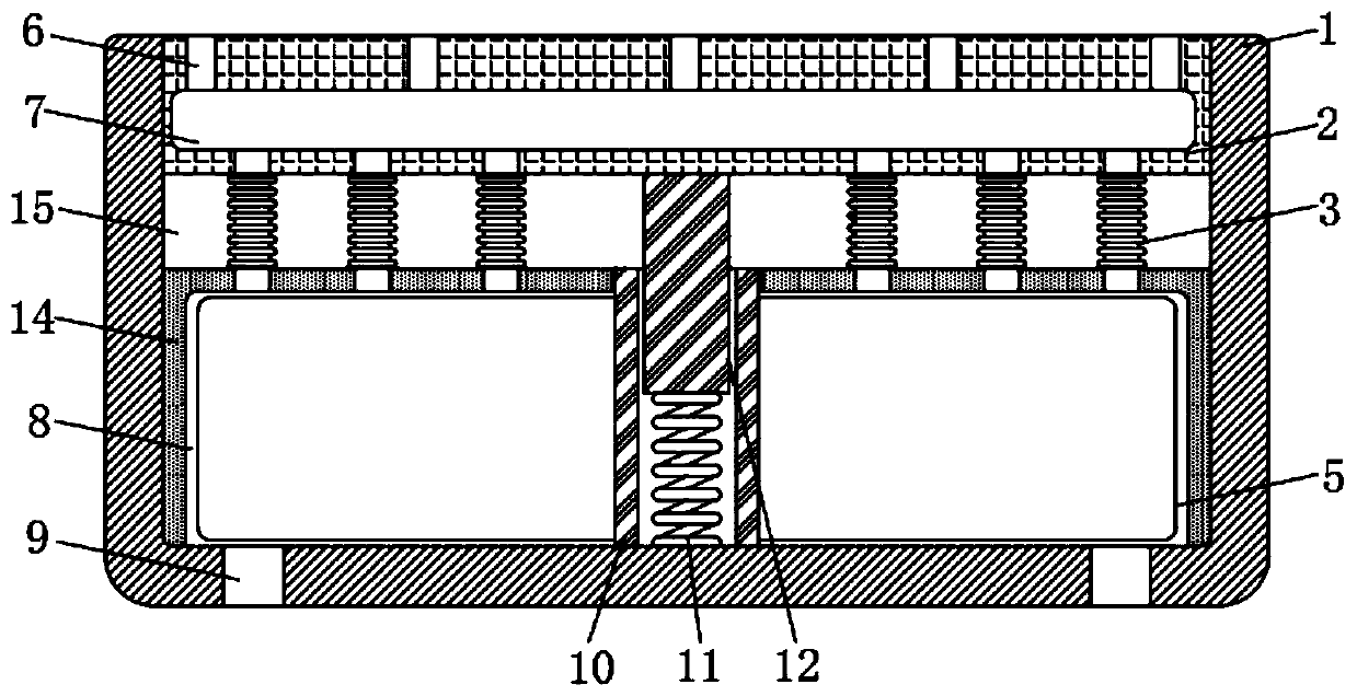

Image

  • Rotary self-water-absorption floor tile
  • Rotary self-water-absorption floor tile
  • Rotary self-water-absorption floor tile

Examples


Embodiment 1

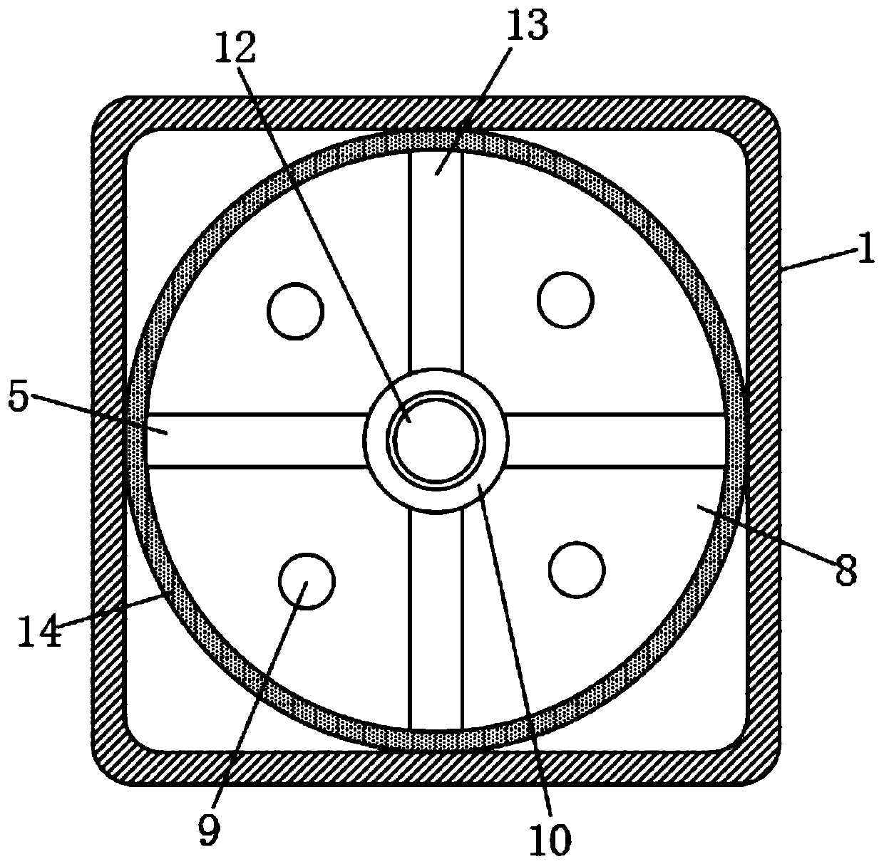
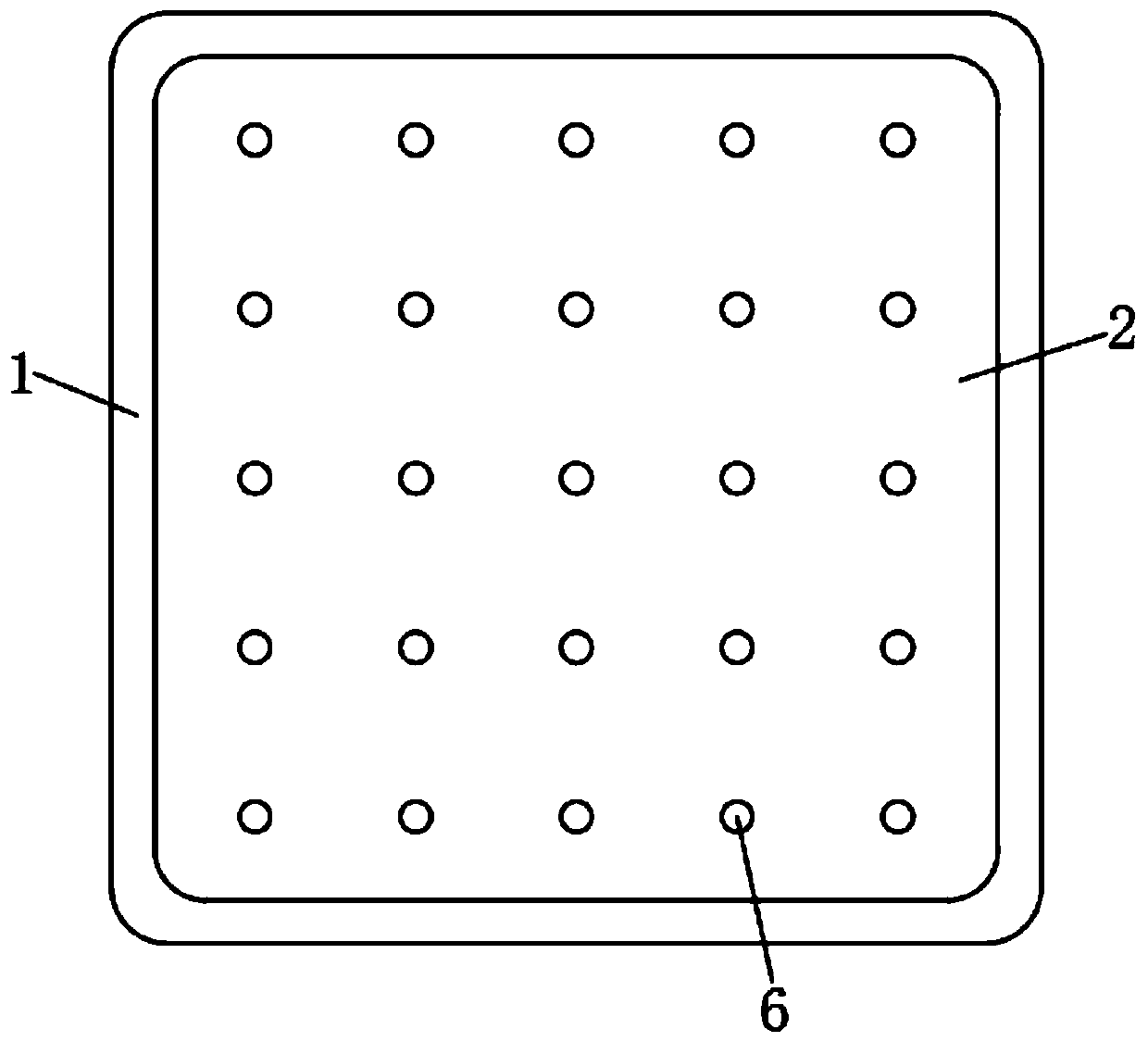
[0022] refer to Figure 1-3 , a rotary self-absorbing floor tile, comprising a hollow brick body 1, the upper end of the brick body 1 is provided with a chute 15, the inside of the chute 15 is sealed and slidably connected with a floating brick 2, and the inner bottom of the brick body 1 is rotatably connected with a sleeve 10 The sleeve 10 is internally threaded with a threaded rod 12 whose upper end is fixedly connected to the lower end of the floating brick 2. The lower end of the threaded rod 12 is elastically connected to the inner bottom of the brick body 1 through a spring 11. A cavity 7 is provided in the floating brick 2, and the floating brick The upper ends of 2 are provided with a water suction port 6 communicating with the cavity 7, and the inside of the brick body 1 is provided with a cylinder 14, the cylinder 14 forms a sealed annular chamber 8 with the sleeve 10 and the inner bottom of the brick body 1.

[0023] The annular chamber 8 is equipped with a negative...

Embodiment 2

[0029] refer to Figure 4-5 , the difference from Example 1 is that: the upper end of the floating brick 2 is provided with a device groove 16, the device groove 16 communicates with the chute 15 through the air guide hole 4, and the position of each device groove 16 does not overlap with the position of the water suction port 6 The upper end of the device groove 16 is fixedly connected with a rubber pad 17, and the inner sealing and sliding connection of the device groove 16 is connected with a sliding plug 19 fixedly connected with the rubber pad 17 through a connecting rod 18.

[0030] When a pedestrian steps on the floating brick 2, the floating brick 2 slides down in the chute 15, thereby extruding the air in the chute 15 into the device groove 16 through the air guide hole 4, and pushing the sliding plug 19 to slide up through the air pressure, and then the rubber pad 17 is jacked up, and the upper end of rubber pad 17 is formed into a convex shape, which can stop and li...


PUM


Abstract

The invention discloses a rotary self-water-absorption floor tile. The tile comprises a hollow tile body, a chute is formed in the upper end of the tile body, a floating tile is connected into the chute in a sealed and sliding mode, a sleeve is rotatably connected to the bottom in the tile body, and a threaded rod with the upper end fixedly connected to the lower end of the floating tile is connected into the sleeve in a threaded mode. A negative pressure mechanism, the threaded rod, the sleeve, a spring, a rubber pad and a sliding plug are arranged, when a pedestrian steps on the floating brick, a water suction port can generate suction force, under the condition that water exists on the floating brick, the water absorption effect can be achieved, under the condition that no water existson the floating brick, a shoe sole can be absorbed, the friction between the shoe and the floor tile is increased, the water absorption and skid resistance effects are achieved, air in the chute is extruded into the device groove, the sliding plug is pushed to move upwards accordingly, the rubber pad is jacked to be in a protruding shape through the connecting rod, the possibility of slipping andtumbling can be eradicated or reduced, accumulated water on the surface of the floating tile can be gathered at the water absorption opening more quickly, and the water absorption effect is improved.

Description

technical field [0001] The invention relates to the technical field of floor tiles, in particular to a rotary self-absorbing floor tile. Background technique [0002] Floor tile is a kind of floor decoration material, also called floor tile, which is made of clay and has various specifications. Floor tiles are firm in quality, pressure-resistant and wear-resistant, and moisture-proof. Some are glazed and have a decorative effect. They are mostly used on the ground and floors of public buildings and civil buildings. [0003] Since most of the floor tiles are fired from clay and have poor water absorption, water is prone to accumulate on the surface of the floor tiles in rainy weather. Once water accumulates on the surface of the floor tiles, pedestrians are prone to slip and fall, especially for the elderly or This is especially true for people with disabilities. Contents of the invention [0004] The purpose of the present invention is to solve the shortcomings in the pr...

Claims


Application Information

Patent Timeline
Patent Type & Authority Applications(China)
IPC IPC(8): E01C11/22E01C15/00E01C11/24
CPCE01C11/225E01C11/24E01C15/00
Inventor 燕燕
Owner 燕燕
Learn More