Feed roller
A technology of paper feeding rollers and convex parts, applied in the field of paper feeding rollers, can solve problems such as poor paper conveying, and achieve the effect of suppressing the generation of paper dust and the poor conveying
- Summary
- Abstract
- Description
- Claims
- Application Information
AI Technical Summary
Problems solved by technology
Method used
Image
Examples
Embodiment 1~18、 comparative example 1~4
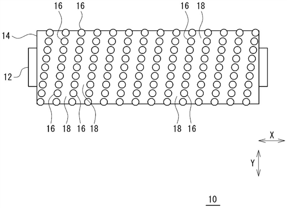
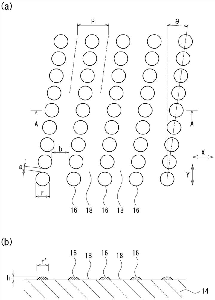
[0079]The core material ( An elastomer layer (thickness: 3 mm) of a urethane rubber composition was formed on the outer periphery of SUS304). From this, it is obtained with Figure 4 or figure 1 The surface shape of the feed roller is shown. That is, on the peripheral surface of the elastomer layer, irregularities are provided by hemispherical protrusions. In embodiment 1, comparative example 1, such as Figure 4 As shown, the hemispherical protrusions are arranged so as to go around along the peripheral surface of the elastomer layer. In other embodiments, comparative examples, such as figure 1 As shown, the hemispherical protrusions are arranged helically along the peripheral surface of the elastomer layer. Further, the row of convex portions and the row of convex portions parallel to the row form continuous grooves of concave portions along the peripheral surface of the elastomer layer. In each paper feed roller, originating from the hemispherical convex portion, ...
Embodiment 19
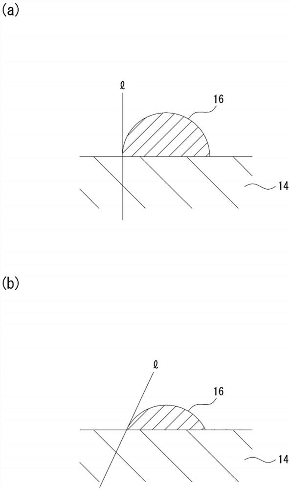
[0090] Made by removing instead of hemispherical convex part Figure 7 A paper feed roller was obtained in the same manner as in Example 2 except for the spherical table-shaped convex portion shown. The upper bottom of the table-shaped convex portion is composed of a ground surface. The table-shaped protrusions are arranged helically along the peripheral surface of the elastomer layer. Further, the row of convex portions and the row of convex portions parallel to the row form continuous grooves of concave portions along the peripheral surface of the elastomer layer. About each size, it is as follows.
[0091] Convex separation distance a: 0.3mm, groove width b: 1.0mm, convex arrangement angle θ: 5°
Embodiment 20
[0093] Made by removing instead of hemispherical convex part Figure 6 A paper feed roller was obtained in the same manner as in Example 2 except for the spherical table-shaped convex portion shown. The upper bottom of the table-shaped convex portion is formed of a flat surface. The table-shaped protrusions are arranged helically along the peripheral surface of the elastomer layer. Further, the row of convex portions and the row of convex portions parallel to the row form continuous grooves of concave portions along the peripheral surface of the elastomer layer. About each size, it is as follows.
[0094] Convex separation distance a: 0.3mm, groove width b: 1.0mm, convex arrangement angle θ: 5°
[0095] Regarding Examples 19 to 20, the measurement of the generation amount of paper dust and the evaluation of durability were performed using the prepared paper feed rollers. The results are shown in Table 3 together with the configuration of the convex portion.
[0096] (Pape...
PUM
 Abstract
Description
Claims
Application Information
 - R&D
- Intellectual Property
- Life Sciences
- Materials
- Tech Scout
- Unparalleled Data Quality
- Higher Quality Content
- 60% Fewer Hallucinations
Browse by: Latest US Patents, China's latest patents, Technical Efficacy Thesaurus, Application Domain, Technology Topic, Popular Technical Reports.
© 2025 PatSnap. All rights reserved.Legal|Privacy policy|Modern Slavery Act Transparency Statement|Sitemap|About US| Contact US: help@patsnap.com


