USB device and operating method thereof

A technology of equipment and terminal resistance, applied in the field of universal serial bus equipment and its operation, can solve problems such as burnout, and achieve the effect of reducing cross-voltage

Active Publication Date: 2020-04-17
VIA LABS INC
View PDF12 Cites 0 Cited by
  • Summary
  • Abstract
  • Description
  • Claims
  • Application Information

AI Technical Summary

Problems solved by technology

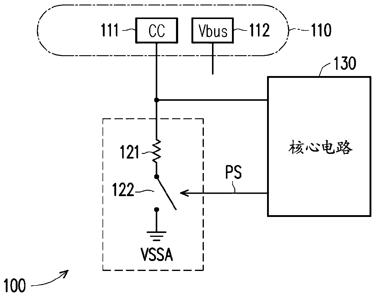
When the high voltage of the Vbus pin accidentally hits the CC pin, this high voltage may burn out the related circuits and / or components connected to the CC pin

Method used


Image

  • USB device and operating method thereof
  • USB device and operating method thereof
  • USB device and operating method thereof

Examples


Embodiment Construction

[0023] As used throughout the specification of this application, including the claims, the term "coupled (or connected)" may refer to any means of connection, direct or indirect. For example, if it is described that a first device is coupled (or connected) to a second device, it should be interpreted that the first device can be directly connected to the second device, or the first device can be connected to the second device through other devices or certain A connection means indirectly connected to the second device. Terms such as "first" and "second" mentioned in the entire specification of this application (including the claims) are used to name elements (elements), or to distinguish different embodiments or ranges, and are not used to limit elements The upper or lower limit of the number is not used to limit the order of the elements. In addition, wherever possible, elements / components / steps using the same reference numerals in the drawings and the embodiments represent ...


PUM


Abstract

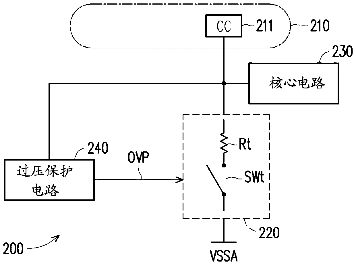
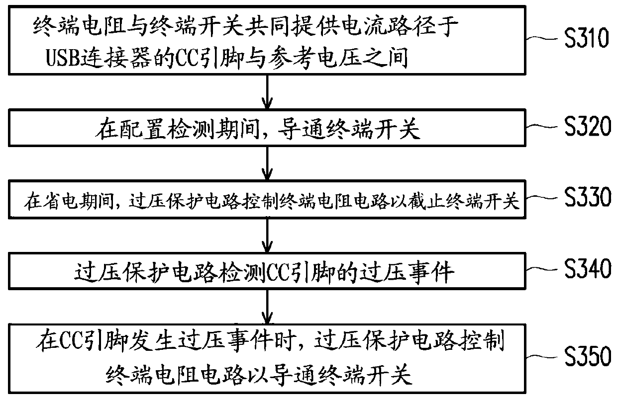
The invention discloses a USB device and an operation method thereof. The USB device comprises a USB connector, a terminal resistance circuit and an overvoltage protection circuit. The terminal resistor circuit comprises a terminal resistor and a terminal switch which are connected in series, wherein the terminal resistor and the terminal switch jointly provide a current path between a CC pin of the USB connector and a reference voltage. During the configuration detection, the terminal switch is turned on. The overvoltage protection circuit controls the terminal resistance circuit to turn offthe terminal switch during a power saving period after the configuration detection period is ended. The overvoltage protection circuit detects an overvoltage event of the CC pin. When the overvoltageevent of the CC pin occurs, the overvoltage protection circuit controls the terminal resistance circuit to turn on the terminal switch.

Description

technical field [0001] The present invention relates to an electronic device, and more particularly to a universal serial bus (hereinafter referred to as USB) device and an operating method thereof. Background technique [0002] The USB connector is a recent popular communication interface. Based on the demand for equipment miniaturization, the size of the USB connector must also be miniaturized. For example, the USB standard organization has proposed a new generation of USB Type-C connector standard to meet the demand for miniaturization. The USB Type-C connector includes configuration channel (configuration channel, hereinafter referred to as CC) pins, power (hereinafter referred to as Vbus) pins and other pins. The Vbus pin can transmit a high voltage (eg, 20 volts or other voltage levels). It should be noted that due to the mechanical structure of the USB Type-C connector itself, the CC pin (CC1 pin or CC2 pin) of the USB Type-C connector is adjacent to the Vbus pin. ...

Claims


Application Information

Patent Timeline
Patent Type & Authority Applications(China)
IPC IPC(8): H03K17/08
CPCH03K17/08G06F2213/0042G06F13/382G06F13/4022H02H9/042H02H9/041Y02D10/00G06F1/3206H02H3/20
Inventor 魏郁忠
Owner VIA LABS INC
Why Eureka
Try Eureka