
Single-phase power factor correction circuit based on three-tube five-level topology

A single-phase power and correction circuit technology, applied in high-efficiency power electronic conversion, output power conversion devices, conversion of AC power input to DC power output, etc., can solve the problems of complex control, insufficient number of levels, and many tubes. , to achieve the effect of simple topology, small voltage stress, and reduced failure loss

Active Publication Date: 2020-04-17
CHINA THREE GORGES UNIV
View PDF12 Cites 5 Cited by
  • Summary
  • Abstract
  • Description
  • Claims
  • Application Information

AI Technical Summary

Problems solved by technology

The existing three-level topology has insufficient levels; the existing five-level topology has a large number of tubes and complex control.

Method used


Image

  • Single-phase power factor correction circuit based on three-tube five-level topology
  • Single-phase power factor correction circuit based on three-tube five-level topology
  • Single-phase power factor correction circuit based on three-tube five-level topology

Examples


Embodiment Construction

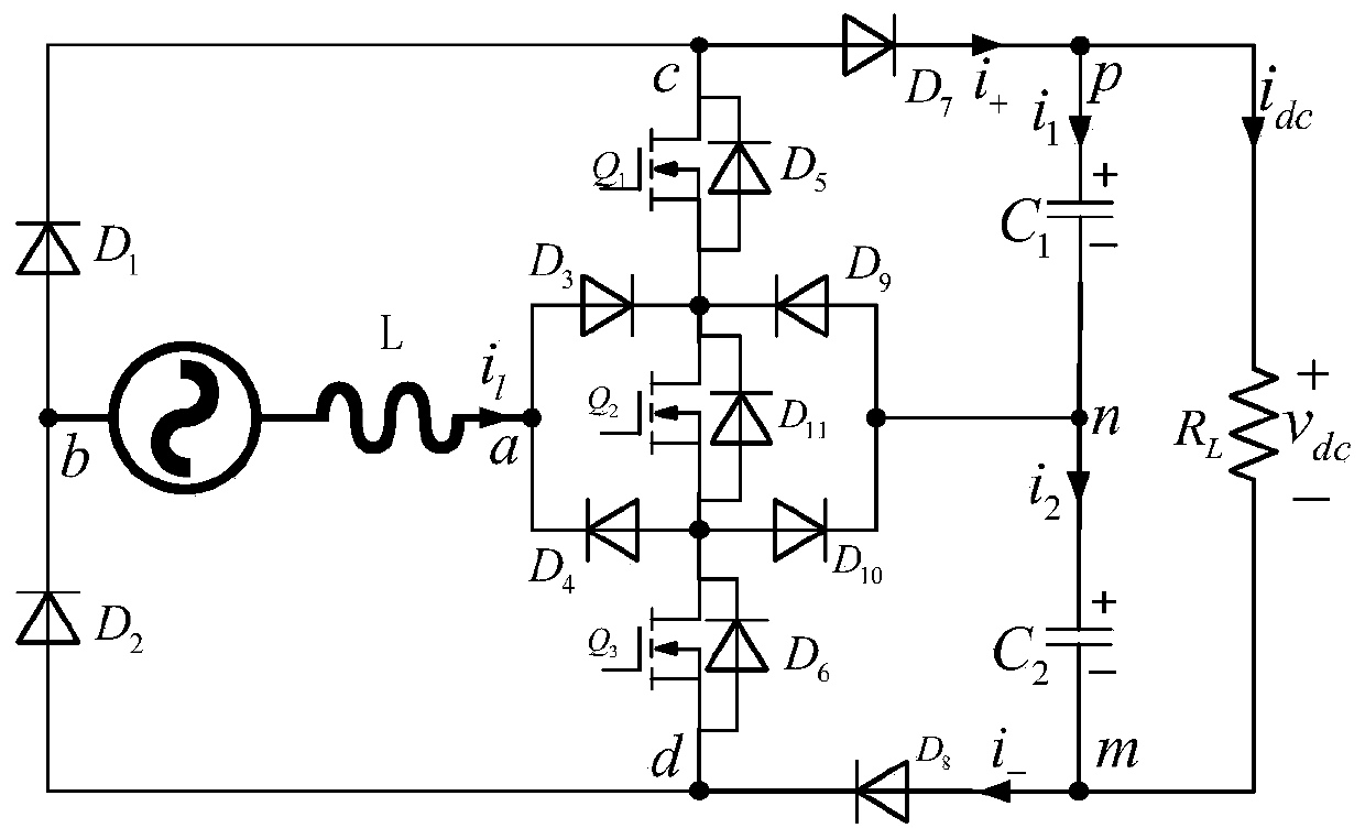
[0042] Such as figure 1 As shown, a single-phase power factor correction circuit based on a three-tube five-level topology includes an inductor L and a switch tube Q 1 , Q 2 , Q 3 , Diode D 1 ~D 11 , Capacitance C 1 , Capacitance C 2 ;

[0043] Connect the diode D to the AC side of the AC power supply 1 Anode, diode D 2 The cathode, the connecting node constitutes the terminal b;

[0044] The other side of the AC power supply AC is connected to one end of the inductor L, and the other end of the inductor L is respectively connected to the diode D 3 Anode, diode D 4 Cathode; the other end of inductor L and diode D 3 , D 4 The connecting node of constitutes the end point a;

[0045] Switch tube Q 2 Connect the drain to diode D 3 Cathode, diode D 9 Cathode, switch tube Q 1 Source

[0046] Switch tube Q 2 The source is connected to diode D 4 Anode, diode D 10 Anode, switch tube Q 3 Drain

[0047] Diode D 7 Cathode connection capacitance C 1 At one end, its connecting nodes constitute an end...


PUM


Abstract

The invention provides a single-phase power factor correction circuit based on three-tube five-level topology. The circuit comprises switching tubes Q1, Q2 and Q3, one side of an AC power supply is connected with the anode of a diode D1 and the cathode of a diode D2, and the connection nodes form an end point b; the other side of the AC power supply AC is connected with one end of an inductor L, and the other end of the inductor L is connected with the anode of a diode D3 and the cathode of a diode D4 and the connection nodes form an end point a; the cathode of the diode D7 is connected with one end of a capacitor C1, and the connection node forms an end point p; the other end of the capacitor C1 is connected with one end of a capacitor C2, and the connection node forms an end point n; theother end of the capacitor C2 is connected with the anode of the diode D8, and the connection node forms an end point m; the drain electrode of the switching tube Q1 is connected with the cathode ofthe diode D1 and the anode of the diode D7 respectively, and the connection node forms an end point c; the source electrode of the switching tube Q3 is connected with the anode of the diode D2 and thecathode of the diode D8, and the connection node forms an end point d. The end point a, the end point c, the end point d and the end point n form four symmetrical ports. The correction circuit adoptsmultiple levels so as to have the advantage that the voltage stress of the switching tube is low.

Description

Technical field [0001] The invention relates to a single-phase power factor correction circuit topology, in particular to a single-phase power factor correction circuit based on a three-tube five-level topology. Background technique [0002] Single-phase high power factor or power factor correction (PFC) boost converters are currently one of the most popular research areas. The main focus of this kind of converter is low unit power factor and low total harmonics. Normally, power factor correction is to apply a boost circuit to achieve power factor correction after rectification. The existing three-level topology has an insufficient number of levels; the existing five-level topology has a large number of tubes and complex control. Summary of the invention [0003] The invention provides a single-phase power factor correction circuit based on a three-tube five-level topology, which is suitable for medium and small power applications. The circuit structure of the invention has the ...

Claims


Application Information

Patent Timeline
Patent Type & Authority Applications(China)
IPC IPC(8): H02M1/42H02M7/217H02M7/155
CPCH02M1/4225H02M7/155H02M7/217Y02B70/10
Inventor 马辉鲁海鹏郑凯通
Owner CHINA THREE GORGES UNIV
Learn More