Flight time based depth camera and three-dimensional imaging method

A technology of depth camera and time-of-flight, which is applied in the field of optics and electronics to achieve the effect of increasing calculation rate, reducing the difficulty of heat dissipation design, and reducing power consumption of light source

Inactive Publication Date: 2020-04-17
SHENZHEN ORBBEC CO LTD
View PDF23 Cites 1 Cited by
  • Summary
  • Abstract
  • Description
  • Claims
  • Application Information

AI Technical Summary

Problems solved by technology

[0003] In order to solve the existing technical problems, the present invention provides a time-of-flight based depth camera and a three-dimensional imaging method

Method used


Image

  • Flight time based depth camera and three-dimensional imaging method
  • Flight time based depth camera and three-dimensional imaging method
  • Flight time based depth camera and three-dimensional imaging method

Examples


Embodiment Construction

[0020] In order to make the technical problems, technical solutions and beneficial effects to be solved by the embodiments of the present invention clearer, the present invention will be further described in detail below in conjunction with the accompanying drawings and embodiments. It should be understood that the specific embodiments described here are only used to explain the present invention, not to limit the present invention.

[0021] It should be noted that when an element is referred to as being “fixed” or “disposed on” another element, it may be directly on the other element or be indirectly on the other element. When an element is referred to as being "connected to" another element, it can be directly connected to the other element or indirectly connected to the other element. In addition, the connection can be used for both fixing function and circuit communication function.

[0022] It is to be understood that the terms "length", "width", "top", "bottom", "front"...


PUM


Abstract

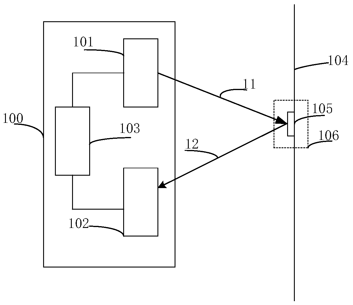
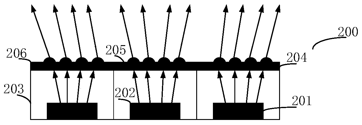
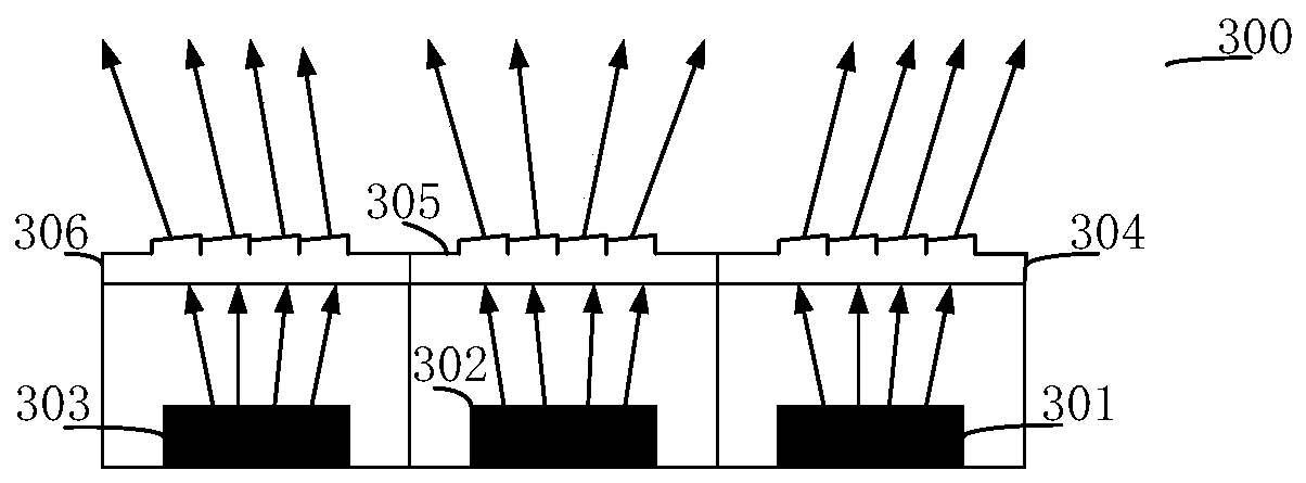
The invention provides a flight time based depth camera and a three-dimensional imaging method, and the depth camera comprises a transmitting module which comprises at least two light sources and is used for transmitting an optical signal, and the optical signal is provided with a certain field angle; a receiving module which comprises an image processor consisting of at least one pixel and is used for acquiring a reflected optical signal; a control and processing module which is used for controlling the transmitting module and the receiving module, processing the optical signals reflected bythe full-view-field area and judging the target area where the target object is located according to the optical signals so as to control the transmitting module to only transmit the optical signals to the target area, and controlling a receiving module to collect an optical signal reflected by the target area and process the optical signal to obtain depth information of the target object; an emission module which has the following characteristics: the first type of illumination refers to scanning an emission optical signal in a full view field area, and the second type of illumination refersto only scanning an emission optical signal in a target area. The method reduces the power consumption of the light source, reduces the power consumption of depth calculation, and improves the calculation rate.

Description

technical field [0001] The invention relates to the technical fields of optics and electronics, in particular to a time-of-flight-based depth camera and a three-dimensional imaging method. Background technique [0002] Based on time-of-flight (TOF) 3D imaging technology, a vertical cavity surface laser emitter (VCSEL) irradiates the target surface with a certain field of view (FOV). When irradiating with full field of view at the same time, in order to improve the signal-to-noise ratio, improve the ranging and imaging accuracy, it is often necessary to increase the peak power of the light source, and the power consumption is relatively large, which increases the design difficulty of the power supply system and heat dissipation system. Because within the FOV range, the target may exist in a very small area, or part of the area, and the rest of the FOV data is not necessary, which consumes a lot of redundant work such as light source and depth calculation, and these redundant ...

Claims


Application Information

Patent Timeline
Patent Type & Authority Applications(China)
IPC IPC(8): G01S17/89G01S17/894G01S7/481G01S7/48
CPCG01S17/89G01S7/4817G01S7/4815G01S7/4816G01S7/4804
Inventor 孙瑞周兴王兆民孙飞马宣杨神武方兆翔
Owner SHENZHEN ORBBEC CO LTD
Why Eureka
Try Eureka