Ultrasonic detection method for judging lubricating state of rolling bearing under actual working conditions

A technology for rolling bearings and actual working conditions, which is applied in the direction of using sound waves/ultrasonic waves/infrasonic waves to analyze solids, instruments, and analysis materials. The effect of machine damage

Active Publication Date: 2020-04-17
CHANGAN UNIV
View PDF8 Cites 3 Cited by
  • Summary
  • Abstract
  • Description
  • Claims
  • Application Information

AI Technical Summary

Problems solved by technology

When the bearing works under lubricating oil lubrication conditions, a lubricating oil film will be formed between the roller and the raceway. Due to the existence of surface roughness, high temperature, low speed, heavy load, chemical reaction, rheological characteristics and other factors in engineering practice, the rolling The full-film lubrication state between the bearing and the raceway fails or is difficult to form, and becomes a mixed lubrication state where fluid lubrication and rough peak contact coexist. The continuous operation of the bearing in the state of insufficient lubrication will significantly reduce the service life and safety. Therefore, the bearing Lubrication state detection has always been the core issue in the field of bearing detection technology
However, due to the limitations of actual working conditions and technical level, a large number of test and detection methods cannot be really applied to the detection of the lubrication state of rolling bearings, resulting in the serious lack of verification and verification of measured data in the existing theoretical development, and it is difficult to truly guide practical applications. , which is one of the key issues to be solved urgently in the development of my country's bearing industry

Method used


Image

  • Ultrasonic detection method for judging lubricating state of rolling bearing under actual working conditions
  • Ultrasonic detection method for judging lubricating state of rolling bearing under actual working conditions
  • Ultrasonic detection method for judging lubricating state of rolling bearing under actual working conditions

Examples


Embodiment Construction

[0024] The present invention will be described in further detail below with reference to the accompanying drawings.

[0025] The present invention provides an ultrasonic detection method for judging the lubrication state of rolling bearings under actual working conditions, comprising the following steps:

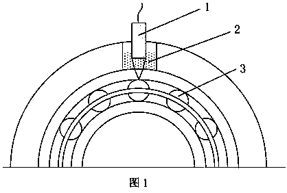
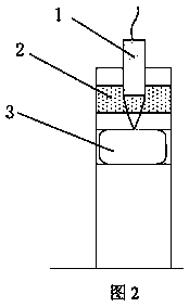
[0026] (1) Selection, installation and adjustment of ultrasonic sensors

[0027] According to the type of test bearing, the working environment of the test, and the speed range, the ultrasonic sensor required for the test is selected. The main parameters include the center frequency of the ultrasonic sensor, the focus diameter (the straight probe is the diameter of the chip), the focal length, temperature range etc. Install the ultrasonic sensor on the bearing seat, and adjust the ultrasonic sensor to a suitable position through the adjustment device (electric or manual multi-degree-of-freedom adjustment platform, etc.), while ensuring good contact between the outer surface...


PUM


Abstract

The invention discloses an ultrasonic detection method for judging the lubricating state of a rolling bearing under actual working conditions. According to the method, a high-frequency focusing probe(or a micro high-frequency normal probe) is arranged on the outer ring of the bearing to obtain ultrasonic reflection echoes of the contact surface of a roller and a ferrule, and the lubrication stateof the bearing is judged according to comprehensive extraction and judgment of the amplitude and phase information of the reflection waves. The detection of the lubricating state of the rolling bearing under the actual working condition is the most direct method for judging the running state of the bearing and is a very key basic detection means in the field of bearing contact lubrication research. Therefore, the lubricating state of the rolling bearing under the real working condition can be detected, and then the lubricating state (dry friction, mixed lubrication or elastohydrodynamic full-film lubrication) between the bearing roller and the ferrule is judged.

Description

technical field [0001] The invention belongs to the technical field of operating state detection of rolling bearings under actual working conditions, and in particular relates to an ultrasonic detection method for judging the lubrication state of rolling bearings under actual working conditions. Background technique [0002] Rolling bearings are widely used in various large rotating mechanical equipment, such as aero-engines, gas turbines, transmissions, machine tools, etc. Its running performance and stability are closely related to the contact lubrication state between inner and outer rings and rollers. When the bearing works under lubricating oil lubrication conditions, a lubricating oil film will be formed between the roller and the raceway. Due to the existence of surface roughness, high temperature, low speed, heavy load, chemical reaction, rheological characteristics and other factors in engineering practice, the rolling The full-film lubrication state between the be...

Claims


Application Information

Patent Timeline
IPC IPC(8): G01N29/04G01N29/11
CPCG01N29/04G01N29/11G01N2291/012
Inventor 李猛田桂斌刘恒王风涛刘意
Owner CHANGAN UNIV
Why Eureka
Try Eureka