
Novel rotary aeration device for sewage treatment

An aeration device and sewage treatment technology, which is applied in the direction of water/sludge/sewage treatment, water aeration, special treatment targets, etc., can solve the problem of affecting normal production, increasing the floor space and investment of spare aeration tanks, and costing money Time-consuming and other issues

Pending Publication Date: 2020-04-17
ZHEJIANG CONSTR INVESTMENT ENVIRONMENTAL PROTECTION ENG CO LTD
View PDF8 Cites 3 Cited by
  • Summary
  • Abstract
  • Description
  • Claims
  • Application Information

AI Technical Summary

Problems solved by technology

[0003] At present, the conventional aeration device is fixedly installed at the bottom of the aeration tank. In the long-term operation, there are the following problems: (1) There are dead angles at the bottom of the aeration pan, resulting in uneven distribution of sludge in the aeration tank, and there will be sludge in the dead angle area (2) It is inconvenient to overhaul, as the aeration pans are all fixedly installed at the bottom of the aeration tank, and the water in the tank needs to be drained for maintenance, and the workers go to the bottom of the tank for maintenance, so that both Affects normal production, and there are potential safety hazards; (3) With the increase of operating time, the oxygenation efficiency of the aerator gradually decreases, until the efficiency decreases to a certain level, it needs to stop production for overhaul, and the aeration tank must be emptied and stopped running during overhaul For more than half a month, it is necessary to design a backup aeration tank to ensure normal production, and the backup aeration tank increases the floor area and investment; (4) All ventilation pipes are arranged in sewage, which is highly corrosive This makes the pipes vulnerable to corrosion, and replacing pipes involves working underwater or emptying the sewage, which is costly and time-consuming, and affects the treatment of the sewage tank

Method used


Image

  • Novel rotary aeration device for sewage treatment
  • Novel rotary aeration device for sewage treatment
  • Novel rotary aeration device for sewage treatment

Examples


Embodiment Construction

[0023] The present invention will be further described below in conjunction with the accompanying drawings and embodiments.

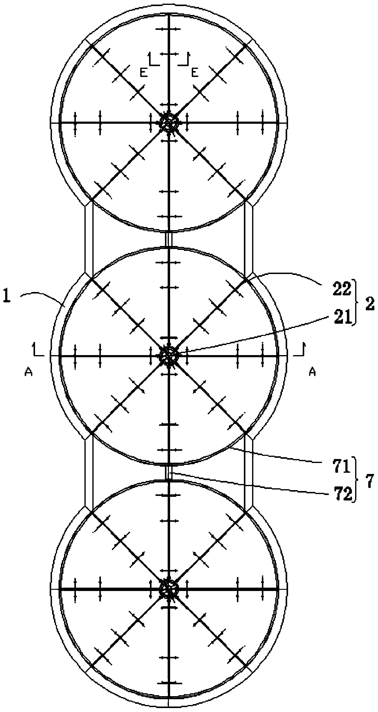
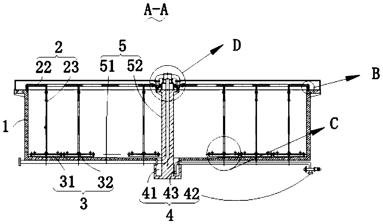
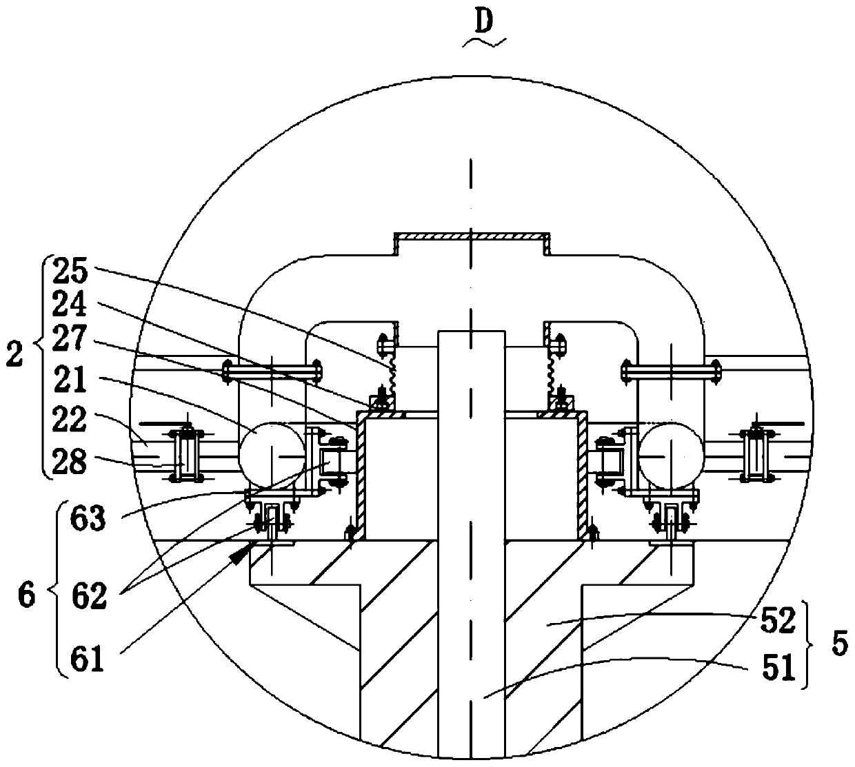
[0024] Please refer to figure 1 , figure 2 , image 3 , Figure 4 and Figure 5 and Figure 6 . in, figure 1 Schematic diagram of the structure of the novel rotary aeration device for sewage treatment provided by the present invention; figure 2 for figure 1 The schematic cross-sectional view of the A-A structure shown; image 3 for figure 2 The enlarged schematic diagram of the structure at D shown; Figure 4 for figure 2 The enlarged schematic diagram of the structure at B shown; Figure 5 for figure 2 The enlarged schematic diagram of the structure at C shown; Figure 6 for figure 1The schematic cross-sectional view of the E-E structure is shown. The novel rotary aeration device for sewage treatment includes: a main body 1 of a treatment pool, the main body 1 of the treatment pool is composed of several arc-shaped and straight-lin...


PUM


Abstract

The invention provides a novel rotary aeration device for sewage treatment. The novel rotary aeration device comprises a sewage treatment tank main body, a connecting mechanism mounted in the middle in the treatment tank main body and comprising an air inlet pipe and a supporting column; and an aeration mechanism comprising an air chamber mounted at the top of the supporting column, wherein the air chamber comprises an air chamber lower part (also serving as a rotary positioning center) fixed at the top of the supporting column and a rotary air chamber upper part, and the air chamber upper part is provided with bent pipes in four directions to be communicated with an annular pipe. A sealing mechanism sealed by graphite packing is arranged between an upper air chamber and a lower air chamber. The annular pipe is connected with eight transverse pipes arranged in a star shape, each transverse pipe is connected with three vertical pipes, each vertical pipe is connected with an aeration pipe, and an aeration disc is connected to the side face of the aeration pipe. The novel rotary aeration device provided by the invention pushes the whole device to rotate by utilizing the counter-actingforce of water when the aeration disc sprays air, and has the advantages of no aeration dead angle, convenience in maintenance, no need of a standby pool and the like.

Description

technical field [0001] The invention relates to the technical field of sewage treatment, in particular to a novel rotary aeration device for sewage treatment. Background technique [0002] The aeration device is the equipment that supplies oxygen to the treatment tank during the sewage treatment process. The purpose of aeration is to make the water obtain enough dissolved oxygen, prevent the suspended matter in the pool from sinking, and strengthen the contact between the organic matter in the pool and microorganisms and dissolved oxygen, so as to ensure that the microorganisms in the pool can oxidize and decompose the organic matter in the water under the condition of sufficient dissolved oxygen. . [0003] At present, the conventional aeration device is fixedly installed at the bottom of the aeration tank. In the long-term operation, there are the following problems: (1) There are dead angles at the bottom of the aeration pan, resulting in uneven distribution of sludge in...

Claims


Application Information

Patent Timeline
Patent Type & Authority Applications(China)
IPC IPC(8): C02F7/00C02F3/02
CPCC02F7/00C02F3/02C02F2303/14Y02W10/10
Inventor 方佩珍何新军朱松徐亮肖敦泉高寒陈姿颖
Owner ZHEJIANG CONSTR INVESTMENT ENVIRONMENTAL PROTECTION ENG CO LTD
Learn More