Machining worktable

A technology of workbench and workbench board, which is applied in the direction of workbench and manufacturing tools, etc. It can solve the problems of affecting the use of tools and reducing the precision, so as to achieve the effect of clean and clean workbench, and reduce sanitary dead angle

Inactive Publication Date: 2020-04-17
嘉兴博立螺丝有限公司
View PDF13 Cites 1 Cited by
  • Summary
  • Abstract
  • Description
  • Claims
  • Application Information

AI Technical Summary

Problems solved by technology

[0002] Some processing that is not suitable or can not be solved by mechanical methods can be completed by fitters, marking, precision machining, inspection and repair in the process of parts processing, component assembly and general assembly, and after adjustment, inspection and test run, etc., to make it To become qualified mechanical equipment, when the machinery fails during use, is damaged or the accuracy decreases after long-term use, and affects the use, it must also be maintained and repaired by the fitter
[0003] The height of the general fitter's workbench is 800mm-900mm, and the surface of the fitter's workbench is smooth and flat, so the box for storing tools is often located at the bottom of the fitter's workbench, and the fitter will use different types and different Roughness, files and other tools of different specifications and shapes, due to the height of the fitter's workbench, the operator needs to bend down to open the tool cabinet to take the tools. If a large number of tools are placed on the table, the powder generated by cutting will also adhere to the tools on, affecting the use of tools

Method used


Image

  • Machining worktable
  • Machining worktable
  • Machining worktable

Examples


Embodiment Construction

[0026] The following will clearly and completely describe the technical solutions in the embodiments of the present invention with reference to the accompanying drawings in the embodiments of the present invention. Obviously, the described embodiments are only some, not all, embodiments of the present invention. Based on the embodiments of the present invention, all other embodiments obtained by persons of ordinary skill in the art without making creative efforts belong to the protection scope of the present invention.

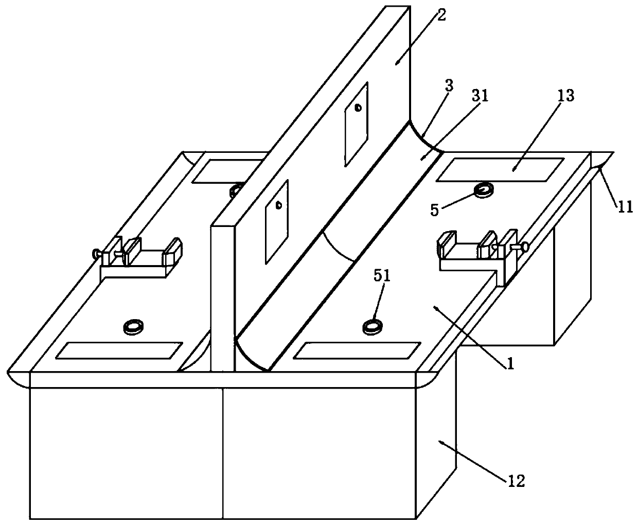
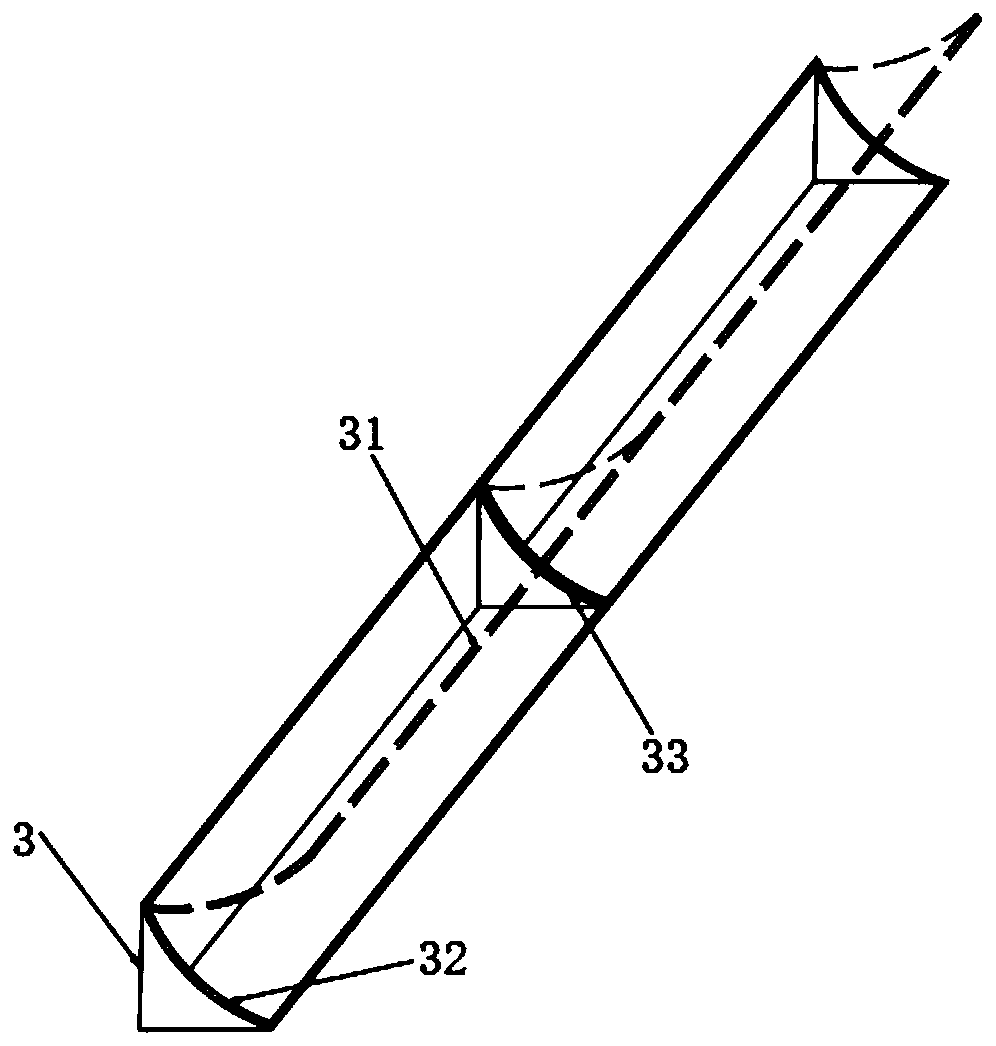
[0027] see Figure 1-6 , the present invention provides the following technical solutions: a processing workbench, comprising two workbenches 1 and a partition plate 2 fixedly connected between the two workbenches 1, the partition plate 2 is located on the upper end surface of the workbench 1 The upper end of the workbench 1 is fixedly connected with a storage box 3, the storage box 3 is located at the corner of the workbench 1 and the partition plate 2, the u...


PUM


Abstract

The invention belongs to the technical field of mechanical manufacturing, and particularly discloses a machining worktable. The machining worktable comprises two worktable plates and a separating plate fixedly connected between the two worktable plates, the separating plate is located on the upper end faces of the worktable plates, a storage box is fixedly connected with the upper end faces of theworktable plates, the storage box is located on the corners of the worktable plates and the separating plate, an observing cover is hinged to the upper end face of the storage box, two symmetrically-distributed supporting storage boxes are fixedly connected to the bottom faces of the worktable plates, through a control switch, a tool box and a document box are controlled to ascend and descend, anoperator is prevented from being affected by the height of the worktable, during object taking, the operator does not need to stoop down or crouch for seeking for, tools used during work are placed in the storage box, the user can intuitively observe the conditions of the tools, and at the moment, on the premise of reducing space occupying of a table board, taking convenience is improved.

Description

technical field [0001] The invention belongs to the technical field of mechanical manufacturing, and in particular relates to a processing workbench. Background technique [0002] Some processing that is not suitable or can not be solved by mechanical methods can be completed by fitters, marking, precision machining, inspection and repair in the process of parts processing, component assembly and general assembly, and after adjustment, inspection and test run, etc., to make it To become a qualified mechanical equipment, when the machine breaks down during use, is damaged, or the accuracy decreases after long-term use, which affects the use, it must also be maintained and repaired by the fitter. [0003] The height of the general fitter's workbench is 800mm-900mm, and the surface of the fitter's workbench is smooth and flat, so the box for storing tools is often located at the bottom of the fitter's workbench, and the fitter will use different types and different Roughness, ...

Claims


Application Information

Patent Timeline
Patent Type & Authority Applications(China)
IPC IPC(8): B25H1/02B25H1/12
CPCB25H1/02B25H1/12
Inventor 沈博文
Owner 嘉兴博立螺丝有限公司
Why Eureka
Try Eureka