Automatic assembling method for snap springs and device

An automatic assembly and circlip technology, applied in assembly machines, metal processing equipment, manufacturing tools, etc., can solve problems such as manual replacement of circlips, gearbox performance failure, uncontrollability, etc., to reduce manual operation workload, labor The effect of reducing the bit beat and improving work efficiency

Active Publication Date: 2020-04-17
SHENGRUI TRANSMISSION
View PDF8 Cites 0 Cited by
  • Summary
  • Abstract
  • Description
  • Claims
  • Application Information

AI Technical Summary

Problems solved by technology

[0003] At present, the position of the circlip in the front-drive 8AT gearbox assembly is as follows: figure 1 As shown, the adjustment circlip 1 is located in the circlip groove 12, and the assembly is generally done manually. Since the manual assembly is to confirm whether it is assembled in place with the naked eye, there is great uncontrollability. Once the circlip is not assembled in place, it will not be fully installed. If it is inserted into the retaining ring groove, there is a risk of falling out. Once the retaining ring falls out, the clutch will fail and the gearbox performance will fail.
[0004] When unqualified products appear after the re-inspection of the circlip re-inspection structure, it is necessary to manually replace the circlip and re-measure, and there is also the risk of placing the replaced circlip in the wrong bin

Method used


Image

  • Automatic assembling method for snap springs and device
  • Automatic assembling method for snap springs and device
  • Automatic assembling method for snap springs and device

Examples


Embodiment Construction

[0025] In order to have a clearer understanding of the technical features, purposes and effects of the present invention, the specific implementation of the present invention will now be described with reference to the accompanying drawings. Those skilled in the art should understand that the following does not constitute a limitation to the protection scope of the present invention.

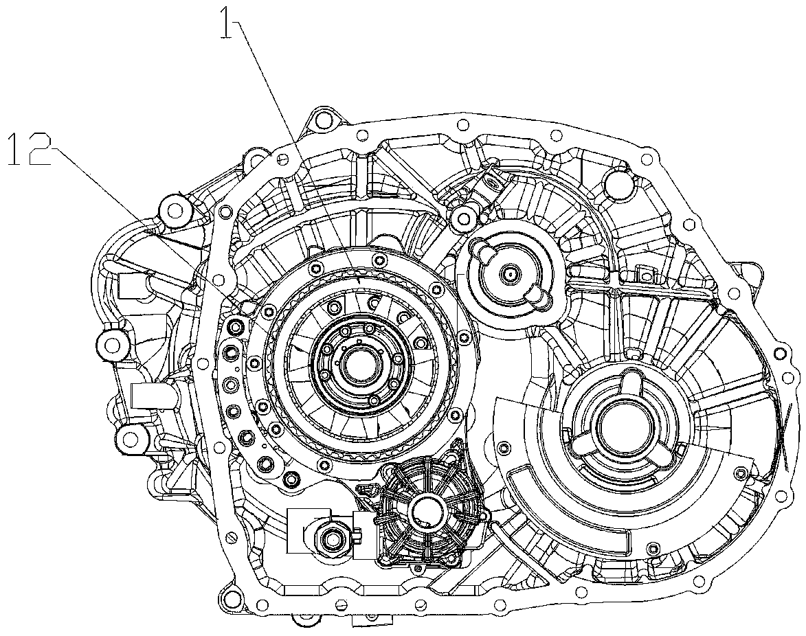
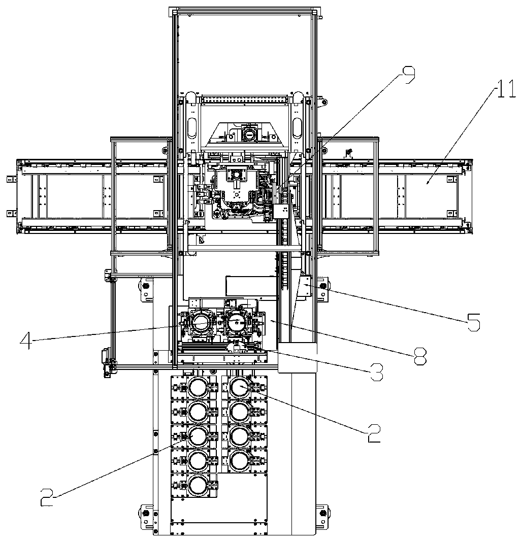
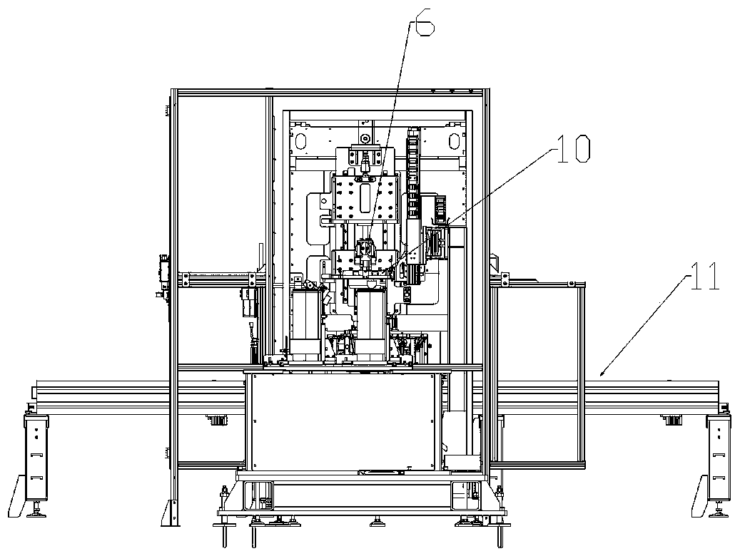
[0026] Examples such as figure 2 , image 3 , Figure 4 As shown, a device for implementing an automatic circlip assembly method includes an adjusting circlip 1 arranged on a bracket 11, a circlip magazine 2, a circlip thickness detection device 3, a circlip receiving device 4, and a circlip picking device. Material device 5, circlip pressure head 6, camera error prevention device 7, circlip retrieving device 9, circlip positioning and ring collection guide device 10 and bracket 11, the adjustment circlip series is generally 10, and the equipment is equipped with 10 clamps Spring feed bin 2, ...


PUM


Abstract

The invention discloses an automatic assembling method for snap springs and a device. The thickness of each of adjusting snap springs is worked out according to a measurement value of a gearbox; the snap rings are automatically discharged by corresponding snap spring bins of the device to a snap spring receiving device; the receiving device transversely shifts to a measuring position; a snap spring rechecking measurer shifts down to measure the thickness of each adjusting snap spring, and if the thickness exceeds the tolerance requirement, a snap spring fetching device takes defective snap springs to a snap spring rejecting device to sift out the defective snap springs; if the thickness meets the tolerance requirement, the snap spring fetching device takes the snap springs to a positioningfixture on a snap spring positioning and receiving ring guide device; a snap spring pressing head shifts down to make the snap springs press-fitted into a snap spring slot through the snap spring positioning and receiving ring guide device; and a photographing mistake-proofing device detects whether the snap springs are press-fitted into the snap spring slot or not. The defective snap springs aregrabbed to a reject bin by a clamping jaw, so that the mixing risk is absent, and the work efficiency is effectively increased; the station beat is obviously reduced; whether the snap springs are fitted into the sap spring slot or not is detected; and once the snap springs are not fitted in place, the device gives an alarm, and the mistake-proofing rate of the mistake-proofing device is 100%.

Description

technical field [0001] The invention belongs to the technical field of automatic transmissions, and in particular relates to an automatic assembling method and device for a circlip. Background technique [0002] Clutches and brakes are assembled to meet the design requirements of the piston stroke by matching and adjusting the circlips, so as to meet the oil pressure requirements of the gearbox and realize gear shifting. Generally, there are about 10 series of circlips, each with a difference of 0.2mm. [0003] At present, the position of the circlip in the front-drive 8AT gearbox assembly is as follows: figure 1 As shown, the adjustment circlip 1 is located in the circlip groove 12, and the assembly is generally done manually. Since the manual assembly is to confirm whether it is assembled in place with the naked eye, there is great uncontrollability. Once the circlip is not assembled in place, it will not be fully installed. If it is inserted into the circlip groove, ther...

Claims


Application Information

Patent Timeline
IPC IPC(8): B23P21/00B07C5/34B07C5/36
CPCB07C5/34B07C5/36B23P21/006
Inventor 王鲁李伦齐杰张启飞张建坤郑健张旗
Owner SHENGRUI TRANSMISSION
Why Eureka
Try Eureka