Motor shaft hole machining device

A hole processing and motor shaft technology, which is applied in metal processing equipment, drilling/drilling equipment, metal processing, etc., can solve the problems of production efficiency, low precision, and impact on feeding efficiency, etc., to achieve stable production cycle and increase Machining accuracy and the effect of improving production efficiency

Pending Publication Date: 2020-04-17
丹东富田精工机械有限公司
View PDF0 Cites 1 Cited by
  • Summary
  • Abstract
  • Description
  • Claims
  • Application Information

AI Technical Summary

Problems solved by technology

[0004] 1. Low efficiency: frequent repetitive work will make people tired, and people's mental state will also affect production efficiency, so it affects the efficiency of material supply;
[0005] 2. High scrap rate: Since the product has positive and negative directions, once the operator is negligent, it will cause waste products, and at the same time, the operator will be distracted by external influences;
[0006] 3. Unable to work continuously for a long time: manual operation will inevitably have rest time, resulting in equipment shutdown;
[0007] 4. Low precision: manual operation is not as stable as machine, and it is easy to cause size deviation
[0009] 1. It cannot be processed continuously. After each workpiece is processed, it needs to be removed, and then the next workpiece is clamped. The processing cannot be carried out continuously, the interval time is long, the labor intensity is high, and the production efficiency is low;
[0010] 2. The stability of the equipment is poor, the size deviation is large, and it is easy to exceed the tolerance and cause waste;
[0011] 3. The clamping efficiency of the chuck is low, which cannot meet the needs of continuous operation;
[0012] 4. The processed workpiece needs to be unloaded manually, which wastes a lot of time

Method used


Image

  • Motor shaft hole machining device
  • Motor shaft hole machining device
  • Motor shaft hole machining device

Examples


Embodiment Construction

[0059] The present invention will be further elaborated below in conjunction with the accompanying drawings of the description.

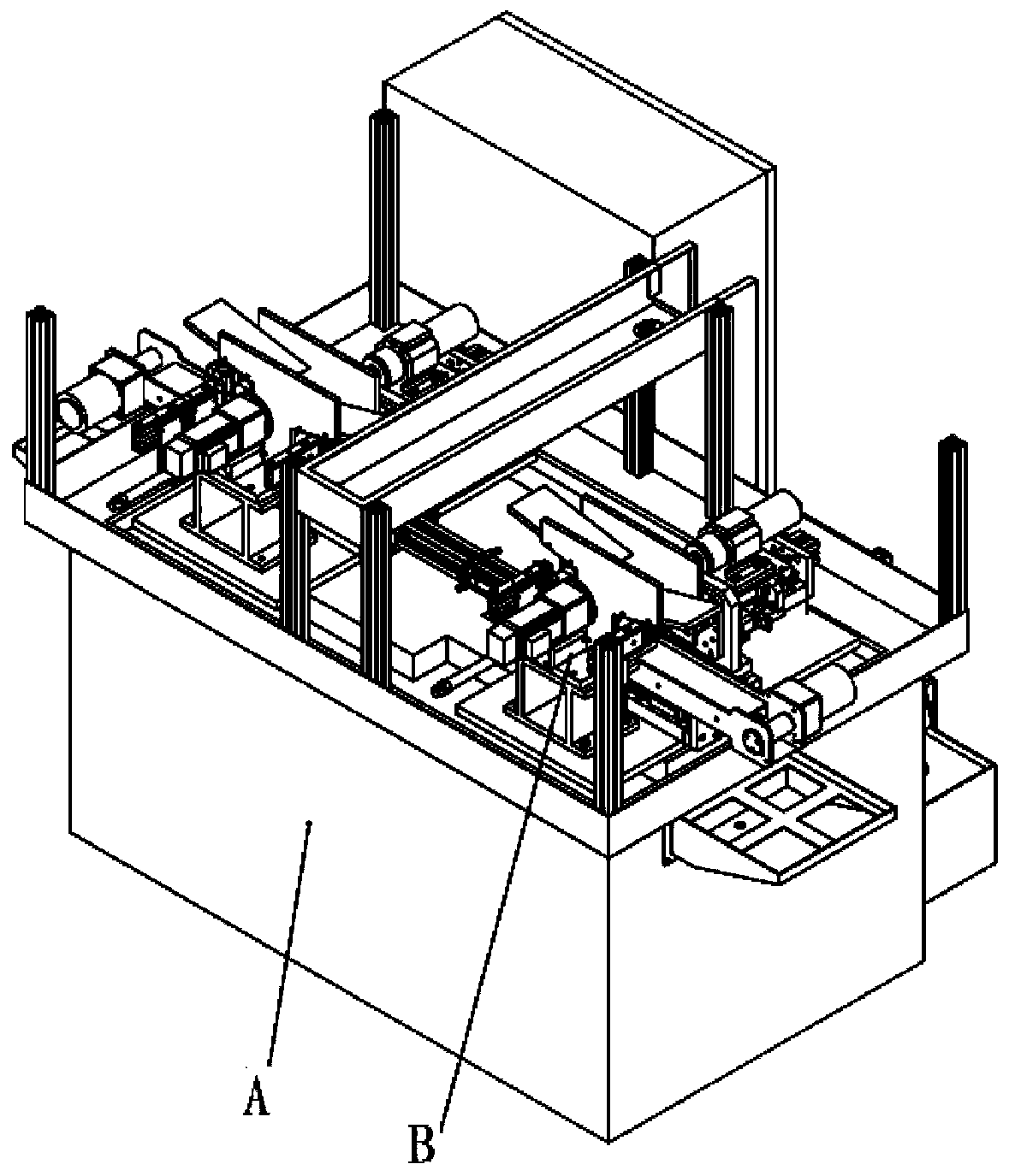
[0060] Such as Figure 2A-2B As shown, the motor shaft hole processing equipment of the present invention includes a bed body A, a mechanism body B, a cutting fluid box C, a spindle coolant box D, and a distribution box E. The mechanism body B is installed on the bed body A, The distribution box E is installed on the side of the bed body A, the cutting fluid box C and the spindle coolant box D are installed in the bed body A; the main body of the mechanism B includes the feeding assembly 1, the drilling assembly 2, and the station conversion assembly 3 And the conveyor belt 4, wherein the drilling assembly 2 is installed on the worktable of the bed body A, the station conversion assembly 3 is installed on the drilling assembly 2, the conveyor belt 4 is installed on the side of the station conversion assembly 3, and the feeding assembly 1 is installe...


PUM


Abstract

The invention discloses a motor shaft hole machining device. The motor shaft hole machining device comprises a bed body, a mechanism body, a cutting liquid box body, a main shaft cooling box body anda distribution box. The mechanism body is installed on the bed body. The distribution box is installed on one side of the bed body. The cutting liquid box body and the main shaft cooling liquid box body are installed in the bed body. The mechanism body comprises a feeding assembly, a drilling assembly, a station conversion assembly and a conveying belt, wherein the feeding assembly, the drilling assembly and the station conversion assembly are installed on a worktable top of the bed body, and the conveying belt is installed on the side edge of the station conversion assembly and under a discharging clamping claw. By means of the motor shaft hole machining device, the machining precision is greatly improved, it can be ensured that a shaft hole and a shaft are concentric and the angle of theconical angle is controlled in an allowed tolerance range, and the rejection rate is reduced; a traditional manual operation machining manner is replaced, the efficiency is greatly improved, the machining precision is high, the labor intensity of operators is lowered, and the rejection rate is reduced; and automatic feeding and discharging are achieved, the device runs continuously, the production takt is stable, and the production efficiency is improved.

Description

technical field [0001] The invention relates to a workpiece processing device, in particular to a motor shaft hole processing device. Background technique [0002] The motor shaft is an important part of the motor product. The machining accuracy and quality of the motor shaft directly affect the overall quality and service life of the motor. Such as Figure 1A-1B As shown, the traditional taper hole processing of the tail of the motor shaft product is usually processed by ordinary lathes through manual operation, which requires manual loading of materials into the fixture, poor stability, low efficiency, and easy waste, which leads to high scrap rate and processing Low precision, high labor intensity and other deficiencies. The main disadvantages are divided into two aspects: [0003] Feeding [0004] 1. Low efficiency: frequent repetitive work will make people tired, and people's mental state will also affect production efficiency, so it affects the efficiency of materia...

Claims


Application Information

Patent Timeline
Patent Type & Authority Applications(China)
IPC IPC(8): B23B41/00B23B47/00B23Q5/26B23Q7/00B23Q7/04B23Q7/14B23Q11/12
CPCB23B41/00B23B47/00B23Q5/26B23Q7/00B23Q7/04B23Q7/1405B23Q11/127
Inventor 田川任孝权
Owner 丹东富田精工机械有限公司
Why Eureka
Try Eureka