
Welding strip correcting device for photovoltaic module laminating machine

A photovoltaic module and laminator technology, which is applied in photovoltaic power generation, electrical components, semiconductor devices, etc., can solve the problems of high use limitations and non-adjustable spacing of the second mounting frame, to ensure accuracy, improve adjustment stability, Improve the effect of the scope of application

Pending Publication Date: 2020-04-17
英利能源(江西)有限公司
View PDF1 Cites 1 Cited by
  • Summary
  • Abstract
  • Description
  • Claims
  • Application Information

AI Technical Summary

Problems solved by technology

A photovoltaic ribbon correction device in the above-mentioned patent has the following disadvantages: when the device is in use, the distance between the second mounting brackets cannot be adjusted, and the position of the ribbon cannot be adjusted according to the demand, and the use limitation is relatively high

Method used


Image

  • Welding strip correcting device for photovoltaic module laminating machine
  • Welding strip correcting device for photovoltaic module laminating machine
  • Welding strip correcting device for photovoltaic module laminating machine

Examples


Embodiment 1

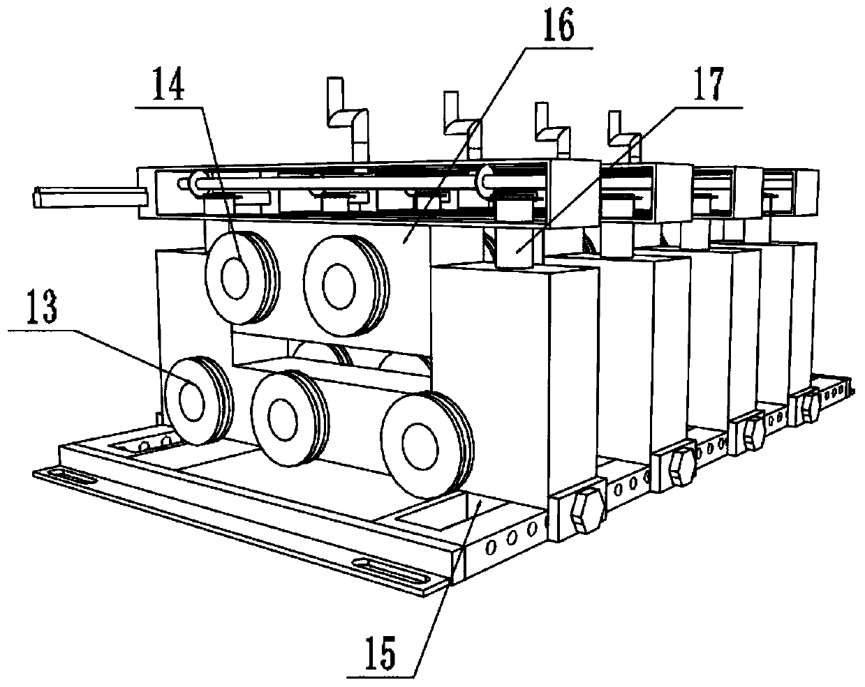
[0027] refer to Figure 1-2 , a welding ribbon correction device for a photovoltaic module laminator, including a connecting frame 1 and a mounting frame 4; a rectangular groove is opened on the top of the mounting frame 4, and a connecting block 16 is slidably connected in the rectangular groove, and one side of the connecting block 16 Several upper roller bodies 14 are fixed on the outer wall through bearings, and several lower roller bodies 13 are fixed on one side of the mounting frame 4 through bearings, and the upper roller bodies 14 and the lower roller bodies 13 are alternately distributed; the top of the connecting block 16 is provided with a lift Assemblies for lifting and lowering the connection block 16, thereby adjusting the distance between the upper roller body 14 and the lower roller body 13 according to the thickness of the welding strip; both sides of the outer wall on one side of the connecting frame 1 are provided with an adjustment frame 3, and the adjustme...

Embodiment 2

[0034] refer to image 3 , a ribbon straightening device for a photovoltaic module laminator, in order to increase the scope of application of the equipment, this embodiment makes the following improvements on the basis of Embodiment 1: the length of the chute 12 is the same as the length of the adjustment frame 3, adjust Both sides of one end of the frame 3 are provided with positioning grooves 18, and both sides of the outer wall of one side of the connecting frame 1 are welded with positioning protrusions, and there are connection fixing holes in the positioning protrusions; the fixed piece 2 can be fixed in the positioning grooves 18; One end of the adjusting frame 3 is fixed with a fixing bar by a screw, so that different numbers of adjusting frames 3 can be installed and fixed through the fixing bar; thus different numbers of mounting frames 4 can be installed as required, which improves the scope of application of the equipment.

[0035] Working principle: According to ...


PUM


Abstract

The invention discloses a welding strip correcting device for a photovoltaic module laminating machine. The welding strip correcting device comprises a connecting frame and a mounting frame, wherein arectangular groove is formed in the top end of the mounting frame, a connecting block is slidably connected in the rectangular groove, a plurality of upper roller bodies are fixed to the outer wall of one side of the connecting block through bearings, a plurality of lower roller bodies are fixed to the outer wall of one side of the mounting frame through bearings, and the upper roller bodies andthe lower roller bodies are distributed in a staggered mode; a lifting assembly is arranged at the top end of the connecting block; and adjusting frames are arranged on the two sides of the outer wallof one side of the connecting frame, sliding grooves are formed in the top ends of the adjusting frames, and sliding blocks are welded to the two sides of the outer wall of the bottom end of the mounting frame. According to the welding strip correcting device for the photovoltaic module laminating machine, the lifting assembly is arranged to be used for lifting the connecting block, so that the distance between the upper roller bodies and the lower roller bodies is adjusted according to the thickness of a welding strip, the height of the connecting block can be adjusted according to the screwing-out length of threaded rods, the threaded rods can be simultaneously adjusted under the action of rotating hand wheel rods, it is guaranteed that the lifting height on the two sides of the connecting block is consistent, and the adjusting stability is improved.

Description

technical field [0001] The invention relates to the technical field of photovoltaic welding strips, in particular to a welding strip straightening device for a photovoltaic module laminator. Background technique [0002] Photovoltaic module laminator is often called laminator, also known as solar cell module laminator. Photovoltaic module laminator usually presses together the layers of glass, EVA, connected double-body battery and back sheet. Mechanical equipment, before the materials are pressed together, the photovoltaic ribbon and the battery sheet need to be welded. During the welding process of the photovoltaic ribbon and the battery sheet, after the ribbon is released from the automatic stringer, the ribbon often bends and The problem of offset is mainly manifested as the distortion and camber phenomenon of the ribbon. In this way, when the cells are processed into cells on the assembly line, there will be a phenomenon that the solder strips are not parallel to the g...

Claims


Application Information

Patent Timeline
Patent Type & Authority Applications(China)
IPC IPC(8): B21D1/02B21C51/00H01L31/18H01L31/048
CPCB21C51/00B21D1/02H01L31/048H01L31/18Y02E10/50Y02P70/50
Inventor 黄良云杨仁森谢淞文
Owner 英利能源(江西)有限公司
Learn More