
Crushing and recycling device for building waste materials

A technology of recycling device and waste material, applied in the field of construction waste material crushing and recycling device, can solve the problems of low efficiency, slow crushing speed, poor recovery effect, etc. Effect

Inactive Publication Date: 2020-04-17
江西振彪建筑工程有限公司
View PDF0 Cites 2 Cited by
  • Summary
  • Abstract
  • Description
  • Claims
  • Application Information

AI Technical Summary

Problems solved by technology

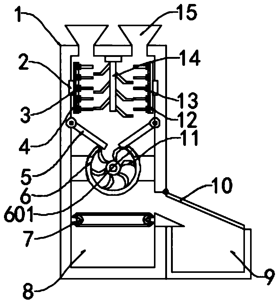
[0003] The present invention aims to solve the problem that the existing construction waste materials are generally piled up randomly by workers without intentionally crushing and recycling them, while the existing construction waste materials crushing and recycling devices cannot fix the cutting knives and cannot adjust the distance of the cutting knives , the cutting and crushing speed is slow, the efficiency is low, and the recycling effect is poor. A construction waste material crushing and recycling device is provided. The device connects the knives to the guide rail through the mounting plate. The movement of the blade changes the interval between the cutters, and the waste material is fully crushed. The waste material is dispersed through the rotation of the stirring rod, so that the waste material is cut more thoroughly, and the cutting efficiency and effectiveness are improved. Through the independent high-speed rotation of the crushing blade , to quickly crush the waste materials in the crushing cylinder. Through the independent rotation of the crushing cylinder, the waste materials and the crushing blades are fully contacted to improve the crushing effect and improve the crushing effect.

Method used


Image

  • Crushing and recycling device for building waste materials
  • Crushing and recycling device for building waste materials
  • Crushing and recycling device for building waste materials

Examples


Embodiment

[0020] see Figures 1 to 3 :

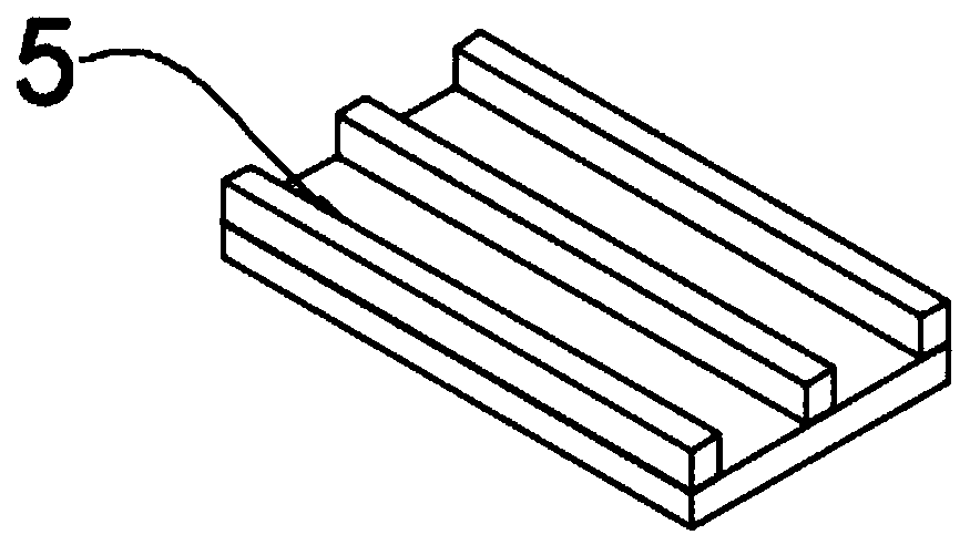
[0021] This embodiment provides a further preferred solution for a crushing and recycling device for construction waste materials, which includes a device main body 1 and a recovery box 9. The top and bottom sides of the device main body 1 are fixedly connected with feeding ports 15, and the upper part of the device main body 1 is fixedly connected with a stirring rod 14. , both sides above the main body 1 of the device are fixedly embedded with a turntable 2, and the outside of the turntable 2 is fixedly connected with a rotating rod 3, and one side of the rotating rod 3 is fixedly embedded with a guide rail 5, and the inside of the guide rail 4 is movably connected with a mounting plate 12, and the outside of the mounting plate 12 The fixed connection is connected with a cutter 13, the left and right sides below the rotating rod 3 are movable with a guide plate 5, the bottom of the guide plate 5 is fixedly connected with a crushing cylinder 6, ...


PUM


Abstract

The invention provides a crushing and recycling device for building waste materials, and belongs to the technical field of construction projects. The crushing and recycling device comprises a device main body and a recycling box, wherein two sides of the top of the device main body are fixedly connected with feeding ports; a stirring rod is fixedly connected to the top of the inside of the devicemain body; rotating discs are fixedly embedded in two sides of the upper part of the device main body; rotating rods are fixedly connected outside the rotating discs; guide rails are fixedly embeddedin one sides of the rotating rods; mounting plates are movably connected inside the guide rails. According to the device, cutters are connected inside the guide rails by the mounting plates, the number of the cutters can be selected as required, spacing between the cutters is changed by movement of the mounting plates in the guide rails, and the waste materials are fully crushed; the waste materials are dispersed by rotation of the stirring rod, and are cut more thoroughly, and cutting efficiency and effect are improved; and the waste materials in a crushing cylinder are rapidly crushed by independent high-speed rotation of crushing blades, and fully contact with the crushing blades by independent rotation of the crushing cylinder, so that the crushing effect is improved.

Description

technical field [0001] The invention relates to the technical field of construction engineering, and more specifically, to a device for crushing and recycling construction waste materials. Background technique [0002] In the process of building construction, different types of building materials need to be used, such as wood, plastic, paper products, etc., and these building materials cannot be fully utilized during use, and waste and damaged materials will inevitably appear, so it is necessary to Construction waste materials are crushed and recycled. Existing construction waste materials are generally piled up randomly by workers without intentional crushing and recycling. However, the existing construction waste materials crushing and recycling devices cannot fix the cutting tool and cannot adjust the distance between the cutting tools. Adjustment, the cutting and crushing speed is slow, the efficiency is low, and the recovery effect is poor. Contents of the invention ...

Claims


Application Information

Patent Timeline
Patent Type & Authority Applications(China)
IPC IPC(8): B02C18/10B02C18/14B02C18/16B02C18/22
CPCB02C18/0084B02C18/10B02C18/14B02C18/16B02C18/2225
Inventor 王彪
Owner 江西振彪建筑工程有限公司
Learn More