Anti-blocking type conversion inlet gas-liquid separator

A gas-liquid separator and anti-clogging technology, applied in the direction of using liquid separation agent, filtration separation, separation method, etc., can solve the problems of scaling and clogging of imported low-pressure waste boiler heat exchange tubes, and achieve the goal of avoiding scaling and clogging Effect

Pending Publication Date: 2020-04-17
ANHUI HAOYUAN CHEM IND GRP
View PDF0 Cites 0 Cited by
  • Summary
  • Abstract
  • Description
  • Claims
  • Application Information

AI Technical Summary

Problems solved by technology

[0005] The invention provides an anti-clogging type conversion inlet gas-liquid separator, which solves the problem of fouling and blockage of the imported low-pressure waste boiler heat exchange tubes during the long-term operation of the gas-liquid separator.

Method used


Image

  • Anti-blocking type conversion inlet gas-liquid separator
  • Anti-blocking type conversion inlet gas-liquid separator
  • Anti-blocking type conversion inlet gas-liquid separator

Examples


no. 1 example

[0036] The present invention will be further described below in conjunction with the accompanying drawings and embodiments.

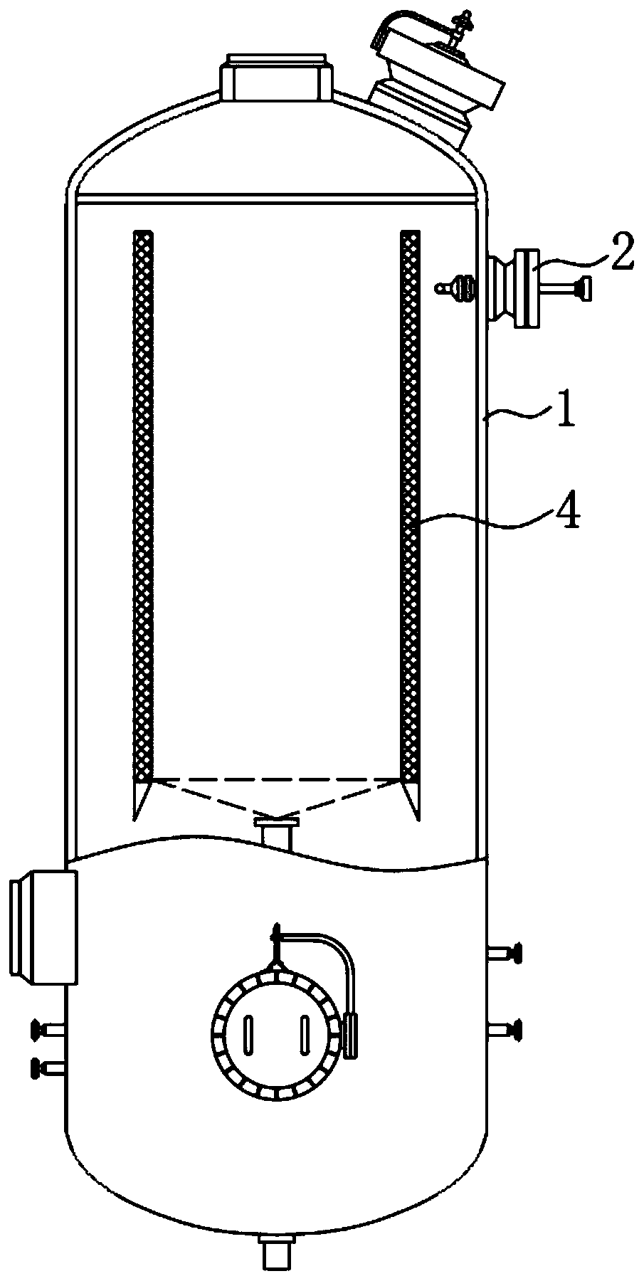
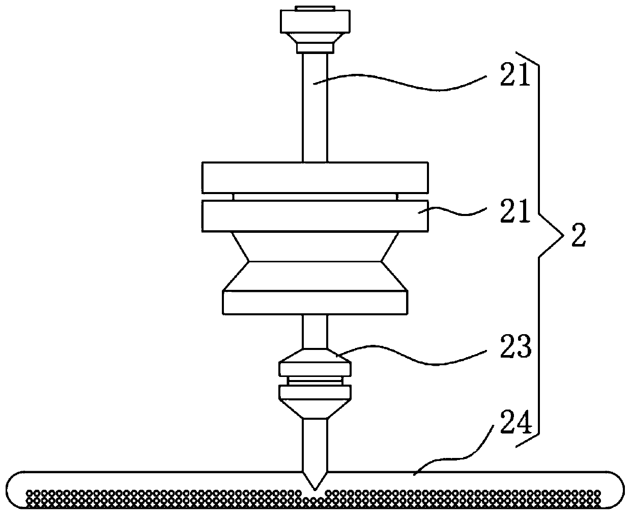
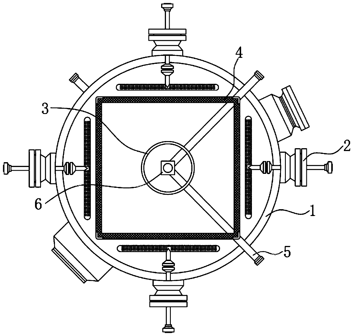
[0037] Please refer to figure 1 , figure 2 and image 3 ,in, figure 1 A schematic structural view of the first embodiment of the anti-clogging type conversion inlet gas-liquid separator provided by the present invention; figure 2 for figure 1 The schematic diagram of the structure inside the tank shown; image 3 for figure 1 Schematic diagram of the structure of the spraying device shown. Anti-clogging variable inlet gas-liquid separator, including:

[0038] Tank 1;

[0039] The spraying device 2, the spraying device 2 is arranged on the tank body 1, the spraying device 2 includes a fixing part 21 and a water conduit 22, and the fixing part 21 is welded on the outer surface of the tank body 1 One end of the water guide pipe 22 runs through the outside side of the tank body 1 and extends to the inside of the tank body 1, and the end of the wat...

no. 2 example

[0049] Please refer to Figure 4-5 ,in, Figure 4 A schematic structural view of the second embodiment of the anti-clogging type conversion inlet gas-liquid separator provided by the present invention; Figure 5 for Figure 4 The enlarged schematic diagram of part A is shown. Based on the anti-clogging type conversion inlet gas-liquid separator provided in the first embodiment of the present invention, the second embodiment of the present invention provides another anti-clogging type conversion inlet gas-liquid separator, wherein the second embodiment does not It hinders the independent implementation of the technical solution of the first embodiment.

[0050] Specifically, the present invention provides another anti-clogging type conversion inlet gas-liquid separator, which is different in that:

[0051] The inside of the fixing part 21 is provided with a rectangular groove 7, the inside of the rectangular groove 7 is provided with a filter device 8, the filter device 8 i...


PUM


Abstract

The invention provides an anti-blocking type conversion inlet gas-liquid separator. The anti-blocking type conversion inlet gas-liquid separator comprises: a tank body; and a spraying device, which isarranged on the tank body and comprises a fixed part and a water guide pipe, wherein one end of the water guide pipe penetrates through one outer side of the tank body and extends into the tank body.According to the anti-blocking type conversion inlet gas-liquid separator in the invention, the spraying device is additionally arranged in original gas-liquid separator equipment; when raw gas enters the separator, an external water source is guided in through the water guide pipe, water pressure is increased through a pressurizer, and then high-pressure water enters a spray header and is finally sprayed out from water outlet holes in the spray header in the form of water mist to spray passing raw gas, so impurities in the raw gas can fall to the bottom of the equipment under the action of the water, and the raw gas with ash can be prevented from entering a subsequent low-pressure waste boiler.

Description

technical field [0001] The invention relates to the field of gas-liquid separators, in particular to an anti-clogging type conversion inlet gas-liquid separator. Background technique [0002] The gas-liquid separator can be installed at the inlet and outlet of the gas compressor for gas-liquid separation, gas-phase demisting after the condensation cooler on the top of the fractionation tower, gas-phase demisting of various gas washing towers, absorption towers and analytical towers, etc., gas-liquid separator It can also be used in various industrial and civil applications such as gas dust removal, oil-water separation and liquid removal of impurities. There are many separation structures used in gas-liquid separators, and the separation methods also include: gravity sedimentation, baffle separation, centrifugal force separation, wire mesh Separation, ultrafiltration separation, packing separation, etc. [0003] In the process of gas-liquid separation of gas, when the gas-l...

Claims


Application Information

Patent Timeline
IPC IPC(8): B01D47/06B01D36/02C10K1/02C10K1/10
CPCB01D36/02B01D47/06C10K1/02C10K1/101
Inventor 高明林王卫锋张超姚迪张辉
Owner ANHUI HAOYUAN CHEM IND GRP
Why Eureka
Try Eureka