
Optical-electrical-optical mode mdi-qkd system synchronization device and method

A synchronization device and optical mode technology, applied in the electronic field, can solve the problems of inability to achieve precise synchronization, inability to ensure stable interference, inability to ensure signal light pulse interference, etc., to overcome the difficulty of delay adjustment and ease of delay adjustment , The effect of high interference stability

Active Publication Date: 2021-08-06
XIDIAN UNIV
View PDF3 Cites 0 Cited by
  • Summary
  • Abstract
  • Description
  • Claims
  • Application Information

AI Technical Summary

Problems solved by technology

However, the disadvantages of this synchronization device are: the synchronization device and method are based on the QKD system at both ends of the BB84 protocol, and the encoding method and synchronization device are too simple. For the MDI-QKD system, the synchronization device and method cannot guarantee the signal light at the Alice end. The interference between the pulse and the signal light pulse at the Bob end at the detection end
However, the disadvantage of this synchronization method is that after the encoding work is completed, the synchronization electrical pulse is not transmitted to the detection end to trigger the work of the single photon detector and the acquisition card, and the synchronization of the synchronization optical pulse at the Alice end and the Bob end cannot be guaranteed. Optical pulses achieve stable interference at the detection end, and precise synchronization cannot be achieved

Method used


Image

  • Optical-electrical-optical mode mdi-qkd system synchronization device and method
  • Optical-electrical-optical mode mdi-qkd system synchronization device and method

Examples


Embodiment Construction

[0042] The present invention will be further described below in conjunction with the accompanying drawings.

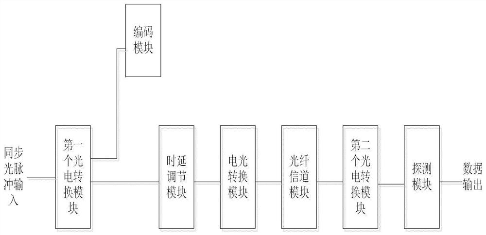
[0043] Refer to attached figure 1 The block diagram of the device further describes the device of the present invention.

[0044] The device of the invention comprises a first photoelectric conversion module, a coding module, a time delay adjustment module, an electro-optic conversion module, an optical fiber channel module, a second photoelectric conversion module and a detection module. The input end of the first photoelectric conversion module is connected to the synchronous optical pulse input from the outside; the output end of the first photoelectric conversion module is connected to the input end of the encoding module; the output end of the first photoelectric conversion module is connected to the delay adjustment The input end of the module is connected; the output end of the delay adjustment module is connected with the input end of the electro-optical conve...


PUM


Abstract

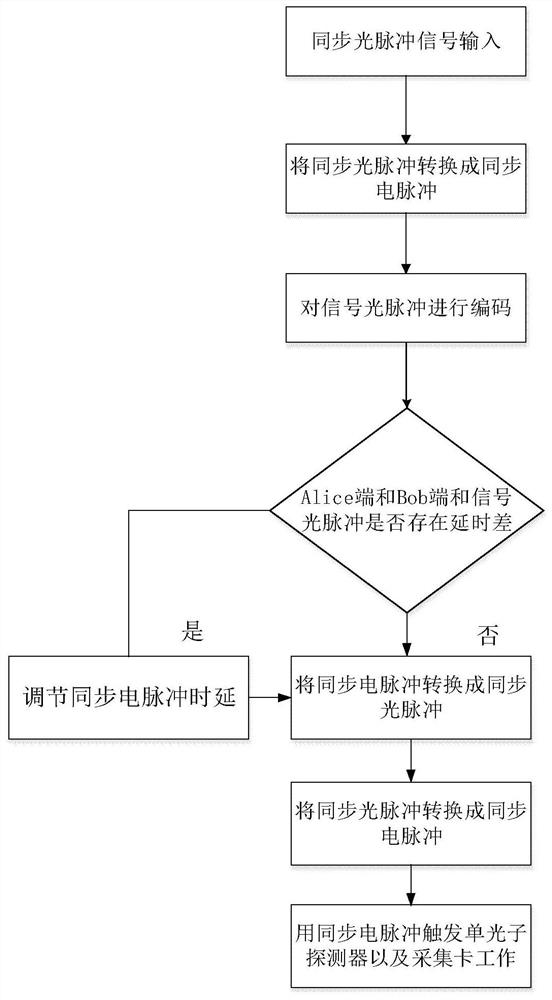
The present invention provides a MDI-QKD system synchronization device and method in optical-electrical-optical mode, the device includes a synchronous optical pulse generation module, a first photoelectric conversion module, a coding module, a time delay adjustment module, an electro-optic conversion module, The second photoelectric conversion module is a detection module. The method includes: transmitting the synchronous optical pulse and the signal optical pulse to the Alice end and the Bob end, and converting them into synchronous electrical pulses, encoding the signal optical pulses, adjusting the time delay of the synchronous electrical pulses, converting the synchronous electrical pulses into synchronous optical pulses and It is transmitted to the detection module and converted into a synchronous electrical pulse, which triggers the work of the single photon detector and the acquisition card. Compared with other ways of generating synchronous electrical pulses in QKD systems, the present invention reduces the problem of high coding complexity, overcomes the shortcomings of interference instability in the prior art, and makes the present invention reliable in transmission, The advantage of high detection efficiency.

Description

technical field [0001] The present invention belongs to the field of electronic technology, and further relates to an MDI-QKD (measurement-device-independent quantumkey distribution) system synchronization device and method in the field of quantum communication technology, which is independent of quantum key distribution in an optical-electrical-optical mode , the invention is used for the synchronization of synchronous light and signal light in the MDI-QKD system to ensure the high detection rate of the single photon detector. Background technique [0002] A key technology of the QKD system is the synchronization of information between the sender and receiver. Only when the signal light and synchronization light are synchronized, can the subsequent key extraction be performed. At the same time, in order to reduce the bit error rate, it is required to remove the dark count as much as possible. In order to ensure the accuracy of single photon counting, it is necessary to acc...

Claims


Application Information

Patent Timeline
Patent Type & Authority Patents(China)
IPC IPC(8): H04L9/08H04B10/70H04J3/06
CPCH04B10/70H04J3/06H04L9/0852H04L9/0858
Inventor 朱畅华刘永平张子健权东晓赵楠何先灯易云辉陈南
Owner XIDIAN UNIV
Learn More